
Tire Technology Overview: Structure, Performance & Manufacturing
1. Introduction
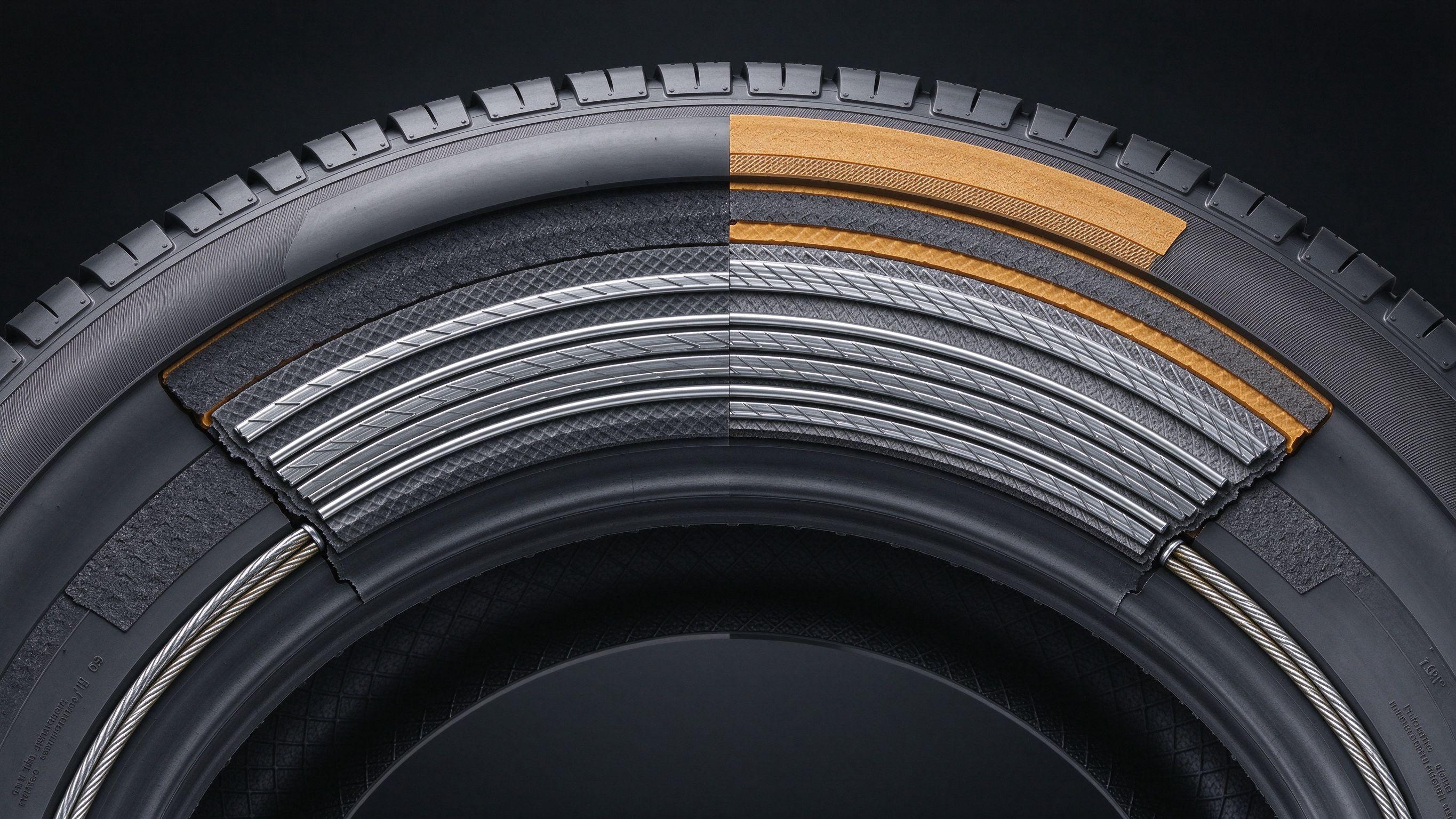
To most consumers, a tire is nothing more than a “round, black consumable that costs a surprising amount.” Tires are widely regarded as low-technology commodities, and buyers often choose purely on price. But anyone who has walked through a tire manufacturing plant comes away impressed: a standard passenger-car radial tire contains more than 20 components and over 15 rubber compounds, and the entire production process demands massive equipment and complex processes to turn raw materials into a finished product.
A tire is a highly engineered composite structure whose performance can be tailored to meet OEM requirements for ride comfort, handling, and grip, while also satisfying consumer expectations for quality and durability. A typical midsize sedan’s wheels rotate roughly 800 times per mile; over a 50,000-mile service life, every component of the tire endures more than 40 million load-unload cycles — an enormous durability demand.
Historically, the pneumatic tire was invented in Britain in the late 19th century as an upgrade over solid rubber tires. Early pneumatic tires had narrow cross-sections and high inflation pressures and were used mainly on bicycles. In the early 1920s, wide-section, low-pressure “balloon tires” arrived, supporting the booming automobile industry. In the early 1950s, rim design advances led to tubeless tires; by the late 1960s, belted bias tires became common. The radial tire — first developed in Europe — entered the U.S. market in the early 1970s and now dominates the passenger-tire market.
This chapter systematically introduces the structure, performance, and testing systems of modern radial passenger-car tires.
2. Basic Tire Theory
2.1 Core Functions of a Tire
(1) The contact surface between vehicle and road
The most fundamental role of a passenger tire is to connect the vehicle to the road. The combined contact patch of all four tires on a typical midsize sedan is actually smaller than a sheet of 8.5 × 11 inch paper; each tire’s footprint is only about the size of an adult palm. Yet this small patch of rubber must deliver safe driving in rain, high-speed cornering on ramps, and survival over potholes.
(2) Supporting vehicle load
Vehicle load deforms the tire until the average pressure over the contact patch balances the internal air pressure. For example, a standard passenger tire inflated to 35 psi carrying a 350 lb load requires about 10 square inches of contact area. Heavier loads demand a larger contact patch (greater tire deformation) or higher inflation pressure; a larger contact patch generally corresponds to a larger tire size. The industry has developed standardized load ratings (see Section 2.3).
(3) Providing road friction
All forces for acceleration, braking, and cornering come from friction between the tire and road. The tread pattern must cope with dry, wet, snowy, and icy conditions. Slick racing tires or tires worn smooth offer excellent dry grip but hydroplane easily in rain and are barely usable. Tread grooves channel water away from the contact patch to reduce hydroplaning, while balancing three competing demands: dry grip, wear resistance, and low noise.
(4) Absorbing road shocks
This is one of the greatest advantages of the pneumatic tire. The tire acts as a spring-damper system, absorbing road impacts and bumps across all driving conditions.
2.2 Tire Classification
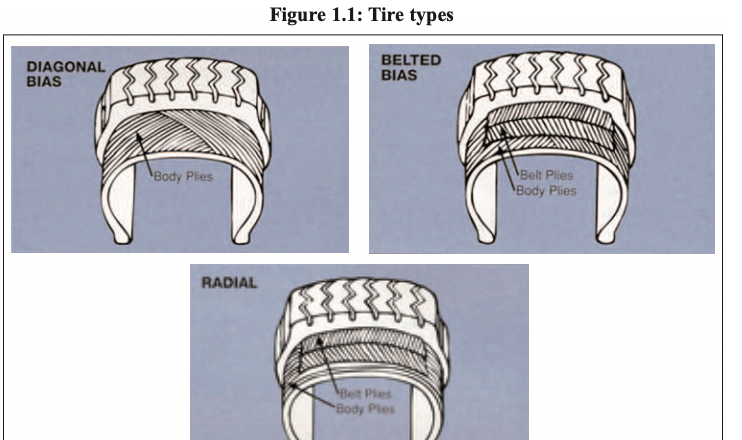
Figure 1.1: Tire structural types — diagonal bias, belted bias, radial
Bias-ply tires are still used in limited applications on trucks, trailers, agricultural machinery, and emerging markets. The carcass plies are laid at a small angle relative to the tread centerline, with cords running from one bead to the other.
- Advantages: Simple construction, lower manufacturing cost.
- Disadvantages: When the tire deforms, shear forces develop between plies, generating heat; large tread deformation leads to poor wear.
Belted bias tires add belt layers under the tread (as the name suggests). The belts restrict circumferential expansion of the carcass, stiffening and stabilizing the tread area.
- Advantages: Improved tread stiffness, better wear and handling.
- Disadvantages: Inter-ply shear heat remains; higher material and manufacturing cost.
Radial tires have carcass cords arranged radially — nearly 90° to the tread centerline — running from bead to bead. Under the tread are two or more belt layers laid at opposing angles for strength and stability. All modern passenger tires use this construction.
- Advantages: Radial cords flex more freely under load, generating less heat, lower rolling resistance, and better high-speed performance; the steel belts dramatically improve tread stiffness, wear, and handling.
- Disadvantages: More complex construction, higher material and processing cost.
2.3 Industry Standards
Size designation system
U.S. tire manufacturers voluntarily join the Tire and Rim Association (TRA), which sets engineering standards for tires, rims, and accessories (inner tubes, valve stems). Industry-wide compliance ensures interchangeability across manufacturers. After radial tires became common in the early 1970s, North America adopted the “P-metric” designation system.
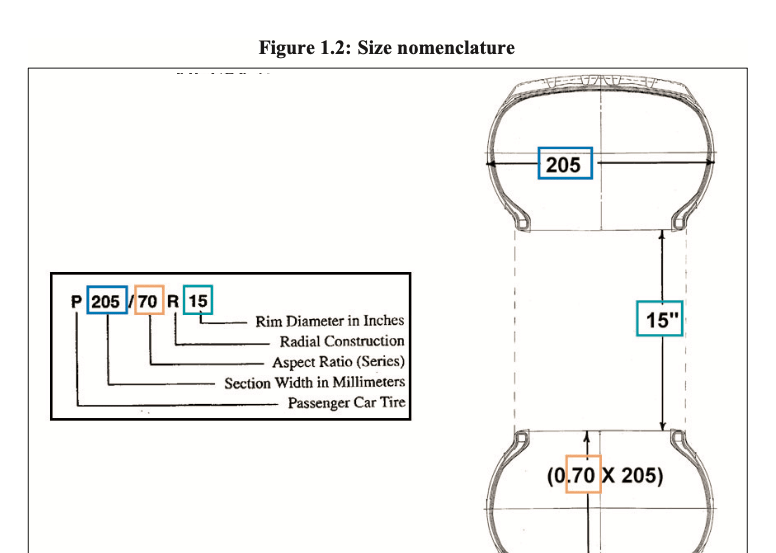
Figure 1.2: Tire size marking explanation
- P — Passenger tire identifier (T = temporary spare; LT = light truck). European sizes generally omit the P/T/LT prefix.
- 205 — Nominal section width in millimeters (unloaded, inflated).
- 70 — Aspect ratio (series number): section height as a percentage of section width. Low-profile series (45/50/55) are used on high-performance vehicles and now also on family cars with larger rims for styling.
- R — Radial construction (D = diagonal/bias; B = belted bias).
- 15 — Rim diameter in inches.
Load capacity
The TRA publishes a load index–load capacity chart, providing a unified basis for matching tire size, load, and inflation pressure (detailed in Chapter 5). The TRA coordinates with the European Tyre and Rim Technical Organisation (ETRTO) and the Japan Automobile Tyre Manufacturers Association (JATMA); for the same size, ETRTO/JATMA and North American P-metric ratings may differ in maximum load capacity.
Load index and speed rating
Most tire sizes carry suffix parameters, e.g., P225/60R15 90H:
- 90 — Load index, corresponding to a specific maximum load weight, used for size interchange matching.
- H — Speed rating; this coding system originated in Europe and was later adopted by the TRA (detailed in Chapter 17).
U.S. federal regulations: DOT 109/110/139
Since 1968, the U.S. Department of Transportation (DOT) has issued passenger-tire regulations: DOT 109 covers indoor testing, tire labeling, and serial numbering; DOT 110 governs OEM tire selection requirements. DOT 109 includes high-speed endurance drum tests, road-impact (plunger) tests, and bead-unseating tests. The 2000 TREAD Act (Tire Recall, Enhancement, Assessment, Documentation) led to the current DOT 139 regulation and revised DOT 110 in 2003 (test details in Chapter 16).
Uniform Tire Quality Grading (UTQG)
Mandated by the U.S. federal government since 1979, all passenger tires (except deep-tread snow tires and temporary spares) must be graded on treadwear, traction, and temperature resistance. All grades are self-tested by the manufacturer, molded on the sidewall, and posted on retail tire labels.
- Treadwear grade: Based on actual road testing. Test tires run 7,200 miles on a 400-mile loop in San Angelo, Texas; wear rate is compared against a reference standard.
- Traction grade: Locked-wheel braking tests on wet asphalt and wet concrete in San Angelo, compared against a control tire.
- Temperature resistance grade: Based on indoor drum high-speed testing, using the same methodology as DOT 109/139 (details in Chapter 17).
3. Tire Components
3.1 Rubber Compound System
Purpose
Beyond the visible tread and sidewall compounds, a tire contains more than a dozen specialized internal compounds, discussed component by component in Section 3.3.
Basic ingredients
- Polymer matrix: The backbone of the compound — natural rubber or synthetic rubber. (Detailed in Chapter 2.)
- Reinforcing fillers: Carbon black is the most widely used; silica and other fillers impart special properties.
- Plasticizers/process oils: Petroleum-based oils, pine tar, resins, and waxes — mainly processing aids that improve uncured tack.
- Anti-aging agents: Waxes, antioxidants, antiozonants that protect against ozone, oxygen, and heat aging.
- Curing system: Sulfur combined with accelerators and activators cross-links polymer chains during vulcanization, converting viscous rubber into a high-strength elastic material.
Balanced compound design
Compounding combines various rubbers, carbon black, silica, oils, waxes, curatives, plus color masterbatches, tackifiers, and hardeners — the possible formulations are enormous. A passenger tire uses roughly 60 raw materials. But formulation changes involve trade-offs: improving one property often worsens another. For example, a tread compound optimized for dry handling may sacrifice wet/snow grip, chip resistance, or rolling resistance. Compounds must therefore be engineered to balance OEM and aftermarket requirements, while remaining cost-competitive and factory-processable.
3.2 Reinforcement Materials
Purpose
Tire reinforcement materials (cords, bead wire) are the primary load-bearing elements of the cord-rubber composite, providing strength and structural stability to the sidewall and tread while containing internal air pressure.
Types and applications
- Nylon 6/66 cord: A synthetic long-chain polymer made by continuous polymerization and melt spinning. In radial passenger tires it is mainly used as cap ply and belt-edge protector, with limited carcass use.
- Advantages: Heat-resistant, high strength, low moisture sensitivity.
- Disadvantages: Sets a static flat spot after cooling; large dimensional growth over time.
- Polyester cord: Synthetic long-chain polymer, melt-spun; the dominant carcass cord for radial tires, with some belt use.
- Advantages: High strength, low shrinkage, low growth, low set, low cost.
- Disadvantages: Lower heat resistance than nylon or rayon.
- Rayon cord: Cellulose wet-spun; used mainly in European tires and run-flat carcasses.
- Advantages: Dimensional stability, heat resistance, excellent handling.
- Disadvantages: Expensive, moisture-sensitive, environmental constraints in production.
- Aramid cord: High-performance organic synthetic fiber, solvent-spun; 2–3× the strength of polyester/nylon; can replace steel for lightweight belts and stabilizer layers.
- Advantages: Ultra-high strength, high stiffness, heat-resistant.
- Disadvantages: High cost, difficult to cut and process.
- Steel cord: Brass-plated carbon steel wire drawn, plated, and twisted into multi-wire bundles — the dominant belt material in radial tires.
- Advantages: Greatly improves belt strength and stiffness, wear and handling.
- Disadvantages: Special processing; susceptible to corrosion if moisture enters.
- Bead wire: Bronze-plated carbon steel wire, drawn and plated, then wound into two annular beads on either side that lock the inflated tire onto the rim.
3.3 Radial Tire Components
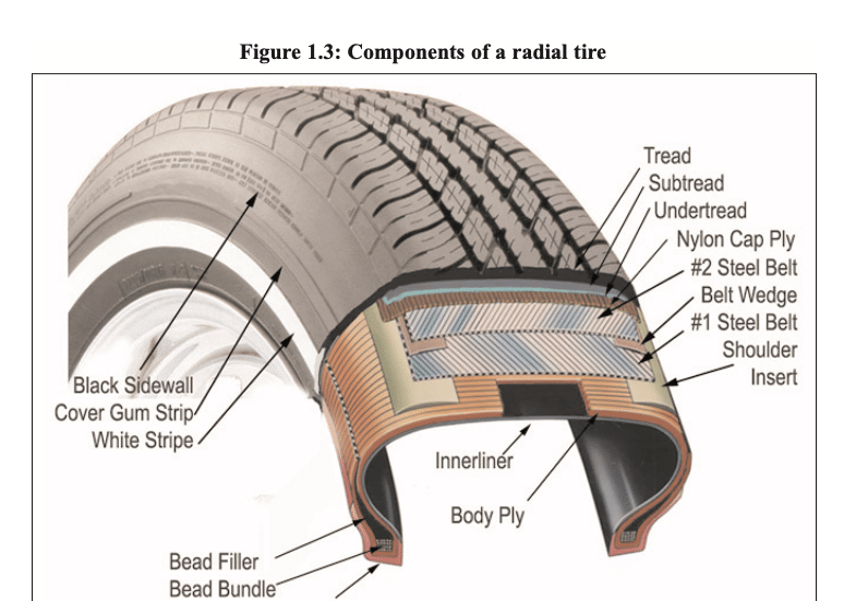
Figure 1.3: Cross-section of a radial tire
- Inner liner: A thin special compound on the inside of tubeless tires that reduces gas permeation and retains air.
- Carcass skim coat: Thin rubber coating the radial cords, calendered onto cord fabric and cut into plies.
- Carcass ply: Cord fabric coated with rubber, wrapped around the bead wires radially from one side to the other. It contains air pressure and resists sidewall impacts. Small tires use one ply; larger sizes often use two.
- Bead bundle: Bronze-plated wire coated with rubber and wound into a ring of specified diameter and structure; anchors the tire firmly on the rim.
- Rim chafing strip: A rubber layer between carcass ply and rim that prevents chafing damage and ensures an airtight seal under all conditions (also called bead filler strip).
- Bead filler (apex): A stiff compound placed above the bead bundle, filling the gap between inner and turned-up carcass plies. Adjusting its height and stiffness tunes ride feel and handling.
- Sidewall compound: Protects the carcass ply from chafing, impacts, and flex fatigue; sidewalls may carry white/colored letters; the compound resists ozone, oxygen, UV, and heat cracking.
- Sidewall reinforcement: Some tires add reinforcement (inserts, turned-up plies, floating layers) in the lower sidewall for stability; run-flat tires use thickened or multi-ply sidewalls to support vehicle load at zero pressure.
- Belt skim coat: Rubber coated on brass-plated steel cords via calender/extrusion, cut at an angle and spliced; formulated for fatigue and tear resistance.
- Belt layers: Two steel-belt layers laid at opposing angles above the carcass and below the tread; they restrict carcass expansion, stabilize the tread, and resist impacts. Adjusting belt width and angle changes ride and handling; variants include three-plus belts and non-metal woven belts.
- Belt wedge strip: A thin rubber strip between belt edges that reduces inter-ply shear stress during rolling deformation.
- Shoulder insert: A contoured rubber strip under belt ends and above the carcass ply that smooths the belt contour and isolates the cord fabric from rigid belt edges.
- Tread: Provides grip for driving, braking, and cornering; the compound balances wear, grip, handling, and rolling resistance. The mold grooves the pattern during curing, designed for even wear, rapid water evacuation to prevent hydroplaning, and low noise on various surfaces. Winter tires use deeper grooves and special compounds for cold, snowy conditions.
- Under-tread cushion: Optional low-hysteresis, low-heat-generation compound extruded under the tread to reduce rolling resistance and meet OEM fuel-economy targets; also fine-tunes comfort, noise, and handling.
- Transition cushion: A thin layer under the tread/under-tread that improves adhesion between tread and belts during curing and covers cut belt ends.
- Nylon cap ply / cap strip: High-speed tires wrap a full nylon cap ply around the belts to suppress centrifugal tread expansion at speed; a narrow strip covering only the belt edges is called a cap strip.
3.4 Radial Tire Design Process
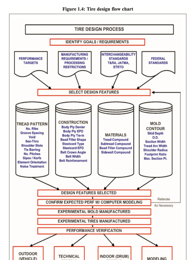
Figure 1.4: Tire design process flow
1. Define design goals and technical requirements
Before formal design, engineers list all product targets: customer performance expectations, manufacturing constraints, internal performance standards, and mandatory national regulations. They also set performance thresholds for every test covered across all chapters. Performance targets derive from market demand or OEM specifications; regulatory targets are mandatory; factory process capabilities limit material and structural choices.
2. Tread pattern design
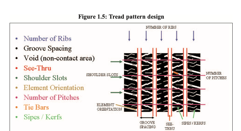
Figure 1.5: Tread pattern design elements
Key pattern elements: rib count and groove spacing determine water evacuation and anti-hydroplaning; through-grooves, void ratio, and shoulder groove size/angle affect grip, handling, and drainage; block count, pitch sequence, sipes, and reinforcing ribs affect grip, noise, and uneven wear.
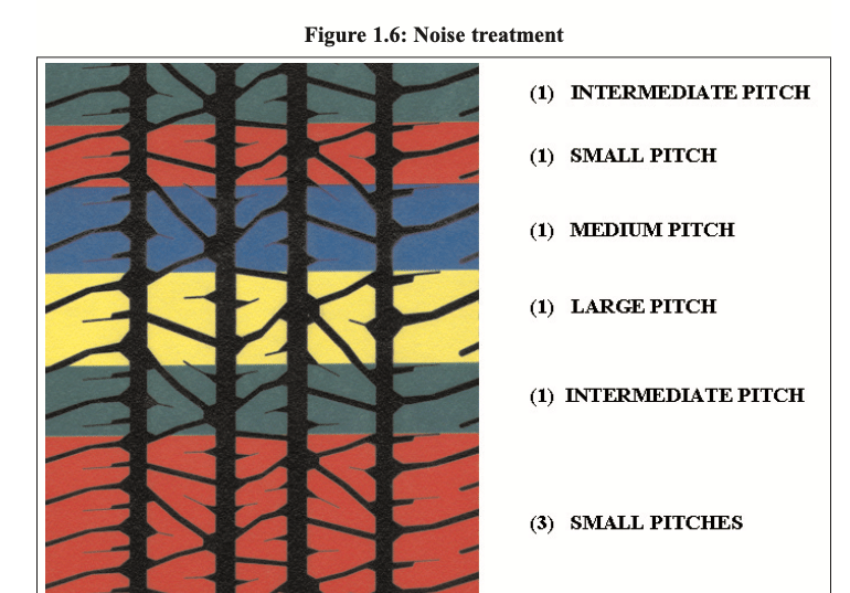
Figure 1.6: Multi-pitch noise reduction design
Multiple unequal pitch lengths are arranged around the tread to eliminate fixed-frequency noise during rotation. Pattern appearance must also match consumer aesthetics and performance expectations.
3. Mold contour design
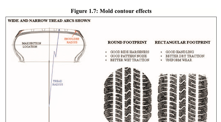
Figure 1.7: Effect of mold contour on contact patch
Mold section width and outer diameter directly determine cured tire dimensions; tread arc, center/shoulder curvature, and groove depth dramatically change performance and can produce entirely different contact patches, affecting ride, wear, and grip.
4. Structural configuration selection
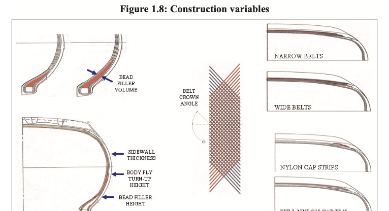
Figure 1.8: Adjustable tire structural parameters
Cord denier, cord specification, ends per decimeter (EPD), and ply count determine carcass strength, selected per production, engineering, and design standards. Steel cord specification and EPD are matched to tire size and use case. Belt width and crown angle change overall longitudinal/lateral stiffness, directly affecting cornering and comfort; high-speed sizes may add edge cap strips or a full nylon cap ply. Bead filler volume/height and carcass turn-up position tune sidewall stiffness, subtly changing handling and comfort.
5. Raw material selection
Tread compound is matched to dry/wet/snow grip while meeting wear and chip-resistance; under-tread compound and thickness are dictated by OEM rolling-resistance/fuel-economy targets; bead filler hardness controls lower-sidewall stiffness, balancing comfort and handling; sidewall compound prioritizes weathering, impact abrasion, and rolling resistance.
6. Structural and performance trade-offs
Size, load, speed rating, carcass/belt materials, compounds, pattern, and structure involve many competing constraints; design must work within TRA, DOT, ETRTO, and internal standards. Engineers rely on design experience, computer simulation, and performance maps to predict target achievement, iterating on structure and materials to find the best compromise for each application.
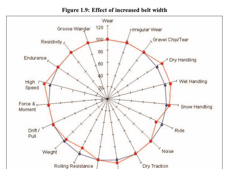
Figure 1.9: Radar chart — effect of belt width on tire performance
For example, widening the belts improves handling and wet grip but worsens comfort, increases rolling resistance, and adds weight. If the customer cannot accept worse comfort and higher fuel consumption, engineers must adjust other structures to compensate. These ongoing trade-offs drive continual iteration in tire materials, structure, and design.
4. Tire Performance Evaluation
4.1 Outdoor Vehicle Testing
(1) Wear rate
Traditional outdoor wear testing: multiple tire sets are driven at a constant speed on specified roads, measuring wear rate in “miles per thousandth inch of tread wear” or “thousandths of inch wear per thousand miles.” Wheel alignment, load, and acceleration/braking magnitude must be strictly controlled for reproducibility; multiple cars run simultaneously to average out road and environmental variation.
(2) Irregular wear
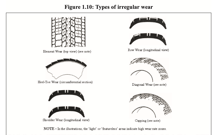
Figure 1.10: Types of irregular tire wear
Irregular wear such as cupping, one-sided shoulder wear, and heel-and-toe wear dramatically shortens tire life. Beyond pattern and structure, wheel misalignment, suspension geometry, hard cornering, rapid acceleration/braking, and under-inflation all accelerate uneven wear. Regular pressure checks, tire rotation, and alignment maximize mileage.
(3) Chip and tear resistance on gravel
Off-road and gravel surfaces can cause tread chunking and tearing in certain compounds/patterns; most outdoor endurance tests include a gravel-road portion to verify this.
(4) Dry/wet/snow handling
Handling is a joint result of tire and vehicle; both engineers and OEMs treat it as a gate test. Metrics: steering response, stability, return-to-center linearity, on-center feel, cornering braking. Tests include lane changes and limit cornering on closed tracks with varied-radius curves, compared by lap time. Wet and dry surfaces are tested separately; snow testing uses a dedicated facility on compacted, groomed snow.
(5) Ride comfort
Tires greatly affect vehicle ride quality. Engineers evaluate not just smooth-road vibration but impacts over joints and railroad crossings, rebound damping after road disturbances, isolation softness, steering-wheel shake, and body vibration. Major tire makers build dedicated test tracks with professional raters. Comfort is a core trade-off: wider belts improve handling but worsen impact harshness.
(6) Noise control
Pattern and structural design invest heavily in noise reduction. Three to seven unequal pitches are arranged around the tread by computer to eliminate fixed-frequency whine. Professional raters distinguish airborne pattern noise from structure-borne noise (amplified through carcass, rim, and suspension), and evaluate low-frequency rumble on rough roads, low-speed braking groan, and hiss on smooth surfaces. Thicker tread and softer apex reduce rough-road noise but increase rolling resistance and alter comfort/handling.
(7) Road groove wander
Many U.S. states (e.g., California) add longitudinal grooves to concrete highways to reduce wet hydroplaning; if these grooves align with tire tread grooves, the vehicle wanders left-right, reducing driver confidence. Engineers adjust groove spacing and reduce rib count on smaller tires to mitigate this.
(8) Pull/drift
On a straight, windless road, the vehicle drifts to one side — tire, alignment, and suspension geometry are all potential causes; the driver must constantly correct the steering, which is unpleasant.
(9) Outdoor endurance testing
Vehicle loaded to rated maximum at standard pressure runs on a closed test track at prescribed speeds in shifts; around the clock, 40,000 miles takes about 45 working days (minus maintenance). Each company has its own proprietary test procedure.
4.2 Indoor Drum Bench Testing
(1) High-speed performance
The industry standard drum is 1.708 m (67.23 in) in diameter — 300 revolutions per mile — used for decades at a constant 38°C (100°F). The mainstream SAE J1561 test loads 80% of rated load, raising speed by 10 km/h every 10 minutes until rated speed or tire failure; starting speed is four increments below the rating. Pressure varies by tire type and speed rating. Standard-load S-rated passenger tires use 260 kPa (38 psi); the reduced load matches the curved drum deformation to flat-road equivalence. DOT 109/139 and UTQG temperature tests use 220 kPa (32 psi) at 85% load, raising one speed increment every 30 minutes (see Chapter 17).
(2) Endurance
High-speed tests hold load constant and ramp speed; endurance tests hold speed constant and ramp load. DOT 109 conditions: 38°C ambient, P-metric radial at 180 kPa (26 psi), constant 80 km/h (50 mph). DOT 139 (mandatory since June 2007) raises speed to 120 km/h (75 mph). Load schedule: 85% max load for 4 hours → 90% for 6 hours → 100% for 24 hours. After the full 34-hour test, an additional low-pressure step: drop to 140 kPa (20 psi) at 100% load for 90 minutes without failure.
(3) Rolling resistance
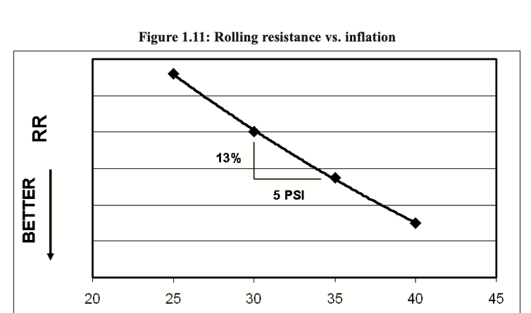
Figure 1.11: Rolling resistance vs. inflation pressure
Rolling resistance is the force needed to overcome tire hysteresis loss; it became a key parameter after U.S. CAFE fuel-economy regulations. Testing uses force transducers on the axle to measure longitudinal resistance; equipment accuracy, calibration, speed, and alignment requirements are extreme for reproducibility. Rolling resistance is expressed as a coefficient (force per unit load); warmed-up OE energy-saving passenger tires run 0.007–0.010. Test load, speed, and pressure vary by OEM request; pressure has a major effect. At highway speed, rolling resistance can consume up to 25% of vehicle power — correct pressure has significant economic value.
4.3 Specialized Precision Tests
- Weight: OEMs set tire weight caps to meet CAFE targets.
- Force and moment: Slip angle generates lateral force that determines cornering capability; test equipment and data analysis are complex (Chapter 8). General models decompose three forces and three moments at the contact patch or axle.
- Electrical conductivity (resistance): Vehicles accumulate static electricity in cold, dry conditions; though rubber is an insulator, it has some conductivity determined by compound. Tire resistance is measured in controlled temperature/humidity labs.
- Uniformity: Material and assembly variation during curing creates small circumferential dimension variations causing stiffness/roundness defects. Uniformity machines measure force variation around the full circumference to match vehicle smoothness/vibration standards.
- Static flat spot: After parking, rubber and cords develop a permanent deformation (“flat spot”). Test: high-speed warm-up and uniformity check → static load on a flat plate for days → re-test uniformity and high-speed run to observe recovery time.
- Dry/wet/snow grip: Instrumented test trailers with computer-controlled braking drag tires on standard surfaces; wheels are gradually locked, recording peak and sliding friction coefficients. Wet tests continuously supply water to the contact patch at controlled film thickness; snow tests use dedicated vehicles on compacted groomed snow for drive traction.
- Air retention: The inner liner compound reduces permeation; rate depends on compound, thickness, temperature, and pressure. Long-term tests run months with temperature control and sealed plumbing. A typical passenger tire naturally loses about 1 psi per month.
4.4 Mandatory Industry and Government Standards
- Dimension standards: Inflated on a standard rim, laser-scanned; section width, outer diameter, and size factor (OD + SW) must meet TRA specs.
- High-speed standard: DOT 139 requires completion of a 160 km/h (100 mph) high-speed test without damage.
- Endurance standard: DOT 139 requires completing the 120 km/h three-stage load endurance test plus a 90-minute low-pressure endurance step, all without failure.
- Bead unseating test: DOT 139 requires a rigid plunger to press the sidewall without air leakage or bead separation from the rim; rim size, pressure, and plunger position are fixed by tire model; revisions are under study.
- Road impact (plunger) test: DOT 139 requires a plunger to slowly press the tread center, recording maximum stroke and impact energy before rupture; multiple points around the circumference must meet minimum energy thresholds. Revisions for low-profile tires are ongoing.
- UTQG grading: U.S. federal mandate — within 6 months of new tire line production, treadwear, traction, and temperature grades must be completed and molded on the sidewall (see 2.3).
5. Tire Manufacturing Process
5.1 Compound Mixing
Raw material intake
Approved suppliers provide raw rubber, carbon black/silica fillers, process oils, and anti-aging agents; the lab samples, codes, and releases them for production.
Internal mixer (Banbury)
Rubber, fillers, oils, and small ingredients are loaded into a closed internal mixer in formulation ratio, 180–500 kg per batch. Material temperature, mixing power, cycle time, and rotor speed are tightly controlled. After mixing, the batch is pressed into slabs or extruded into pellets for storage and later blending.
Open mill
Wide-gap water-cooled rolls work the compound, blending multiple batches to prepare for extrusion and calendering.
5.2 Component Preparation
Calendering
Looking like a larger mixing open mill, multiple rotating rolls press rubber into uniform sheets of specified thickness, tolerances within 0.001 inch. Sheets become inner liner, chafing strip, and belt wedge, or are used to produce rubber-coated carcass/belt cord fabric.
Carcass ply preparation
Nylon, polyester, rayon, and aramid yarns are twisted into cords, woven into wide-width greige fabric, dipped in latex to improve rubber adhesion, and heat-set under tension. Output is a roll about 57 inches wide and 3,000 yards long, matching specified denier and EPD.
A 4-roll calender applies skim coat to both sides, winding 350-yard rolls separated by polypropylene film. Since calendered cords run along the roll length but radial tires need transverse cords, the roll is bias-cut 90° and spliced end-to-end.
Steel belt calendering
Brass-plated steel cord bundles are creeled in a temperature/humidity-controlled room, calendered with rubber on both sides, then bias-cut and spliced; belt #1 and #2 use opposite widths and angles, produced separately.
Nylon cap ply calendering
Similar to carcass ply: wide nylon greige fabric is calendered with rubber; no 90° rotation needed — just slit to width.
Bead bundle preparation
Bronze-plated single wire is extrusion-coated with rubber, then wound to specified diameter and structure; apex may be pre-applied for assembly efficiency. Some makers use cable-bead processes.
Extrusion
Tread, sidewall, and other profiled components are pushed through a screw extruder; multiple screws co-extrude different compounds. The die controls the profile; extrusions get color-coded to identify specs; tread is cut to length, other rolls are film-wrapped for storage.
5.3 Tire Building and Assembly
Stage 1: Carcass building
An expandable rotating drum first lays inner liner and carcass ply, positions beads and apex, turns up the ply around the beads, and applies sidewall compounds on both sides; the drum contracts and the green carcass is removed.
Stage 2: Belt and tread assembly
On a separate drum, two steel belt layers and a nylon cap ply are wrapped, then the extruded tread assembly is applied.
Green tire forming
Stage-2 equipment expands the carcass over the belt/tread package and rollers press all components together to form the uncured green tire, which is transferred to curing. Fully integrated high-volume builders combine multiple steps for higher efficiency, but a line stoppage halts everything.
5.4 Curing (Vulcanization)
Curing press
Large curing machines weigh over 20 tons, with steam, vacuum, and water connections, automatic loading/unloading; an internal bladder inflates to press the green tire against the mold wall.
Mold types: Full round / segmental
- Full-round mold: Split in half; suited to bias tires; tread deforms a lot on opening, making low-profile tire demolding difficult.
- Segmental mold: Tread splits into 8–9 radial segments; green tire expansion is small, segments retract away from the tire — suited to low-profile, low-rolling-resistance radial tires.
Vulcanization reaction
The bladder presses at several hundred psi against the mold; high-temperature steam heats for 12–15 minutes. Rubber cross-links via vulcanization, turning from viscous compound into a high-strength elastic product; temperature, pressure, and time are computer-controlled.
5.5 Final Inspection
- Trim vent spews: Mold vent holes form rubber “sprues” during curing; rotating knives trim them uniformly.
- Visual inspection: Human inspectors check for bubbles and voids; minor defects can be ground and repaired, severe ones are scrapped.
- Uniformity check: Every tire is laser-scanned for circumferential force variation to match vehicle vibration standards.
- White letter/sidewall buffing: A grinding wheel removes the black protective film from white decorative sidewall rubber to expose clean white markings.
5.6 Quality Control Testing
- Production approval testing: A new line must pass the full battery of destructive, indoor, and outdoor tests before mass production.
- Ongoing sampling: Statistical process control plus periodic sampling keeps finished-product performance stable.
6. Consumer Tire Care Guide
6.1 Maintain Recommended Inflation Pressure
U.S. regulations require vehicles from 2006 onward to show OEM recommended pressure on the B-pillar placard; older cars have placards on the door, glove box, or trunk. The tire sidewall molds maximum load and corresponding pressure. A radial tire 12 psi under-inflated still looks nearly normal; rubber naturally loses about 1 psi/month, faster in heat or after punctures. Under-inflation accelerates uneven wear, raises fuel consumption, and overheats — leading to blowouts. Check pressure monthly when cold, and before long trips or heavy loads; pressure drops about 1 psi per 10°F temperature drop; replace valve stems when installing new tires.
6.2 Never Overload
The vehicle placard lists Gross Vehicle Weight and front/rear axle rated loads. Overloading increases tire deformation and heat, greatly raising failure risk (see Chapter 15).
6.3 Regular Rotation and Wheel Alignment
Rotate tires every 6,000–8,000 miles to balance wear and extend life; the first rotation on new tires matters most. Follow sidewall rotation arrows for unidirectional/asymmetric tires. Misalignment directly causes irregular wear; rear alignment on independent rear suspensions is equally important — computer alignment checks thrust angle. Correct pressure + regular rotation + precise alignment = maximum tire life.

Leave a Reply
Want to join the discussion?Feel free to contribute!