
Tire Load Capacity: TRA Formula History & Proposed Revision
Tire Load Capacity: The TRA Load Formula and a Proposed Revisions
This chapter traces the evolution of the TRA (Tire and Rim Association) load-carrying capacity formula for passenger tires, compares it with an alternative approach based on constant relative deflection, and proposes a new formula better suited to modern low-profile, large-rim tires.
Keywords: tire load capacity; TRA formula; tire deflection; tire stiffness; load index; rolling circumference
1. Introduction
Since its founding in 1903, the Tire and Rim Association (TRA) has set tire interchangeability standards covering load, dimensions, rim contours, and valves. The load formula is empirical, derived from member-company data and field experience. For a given pressure, the load limit is the maximum rated capacity; conversely, the listed pressure is the minimum recommended for that load. The formula’s goals are: (a) enable interchangeable tires across manufacturers; (b) provide progressive load ratings within a product line; (c) balance OEM requirements with real-world service.
2. History of the TRA Load Formula
Before 1928, load ratings were negotiated by manufacturers. Loads were independent of rim diameter, proportional to section width, and directly proportional to inflation pressure: L = L₀(P/P₀). In 1928, rim diameter was introduced. The first formal formula was developed by mathematician C.G. Hoover in the mid-1930s, incorporating pressure, section width, and rim diameter — designed to maintain uniform deflection across tire sizes.
The early “low-pressure passenger tire” formula was:
Revised in 1936 to:

Since then, the input parameters (section width S, rim diameter DR, pressure P) have remained the framework; only coefficients and exponents have been adjusted for new tire types and metrication.
3. Derivation of the Base Formula
Schuring (1985) reconstructed the logic: the load-pressure relationship was made sub-linear with exponent n = 0.585, and load was assumed proportional to internal air volume V. Early tires had near-circular cross-sections where V ∝ S²(DR + S), leading to:
Because torus volume is not strictly proportional to S², the exponent was reduced from 2 to 1.39 based on field experience:

4. The Constant K (Service Factor)
The coefficient K adjusts for tire type and service condition: truck/bus tires use K=1.00; passenger tires originally used K=1.10. The 0.425 factor was introduced to bring K near 1.00. When P-metric tires were introduced in the 1970s, metric conversion constants were merged into a revised K.
5. Pressure Exponent
The exponent 0.585 limits how quickly load grows with pressure — as pressure rises, tire stresses increase, so a sub-linear exponent caps deflection and stress. When P-metric tires were introduced, the exponent was reduced to 0.50. P-metric design load pressure rose from 26 psi to 28 psi; max load pressure from 32 psi to 35 psi.
6. Section Width (Equivalent Section Diameter)
Early tires had circular cross-sections (aspect ratio = 1.00). As tires became wider and lower-profile, the cross-section became elliptical. An equivalent section diameter Sd was introduced to preserve the circular-section calculation logic — the perimeter of an elliptical cross-section is converted to an equivalent circle.
7. Why a Formula Review Is Needed
Tire sizes have proliferated dramatically: from 91 sizes in 1975 to 145–345 by 2003; aspect ratios now range from 30 to 80; rim diameters from 12 to 22 inches. The original formula assumed circular cross-sections. Meanwhile, TPMS regulations allow tires to run at reduced pressure (increased deflection) before warning. The current formula unfairly penalizes large-rim, low-profile tires.
8. A New Research Approach: Load–Deflection and Stiffness
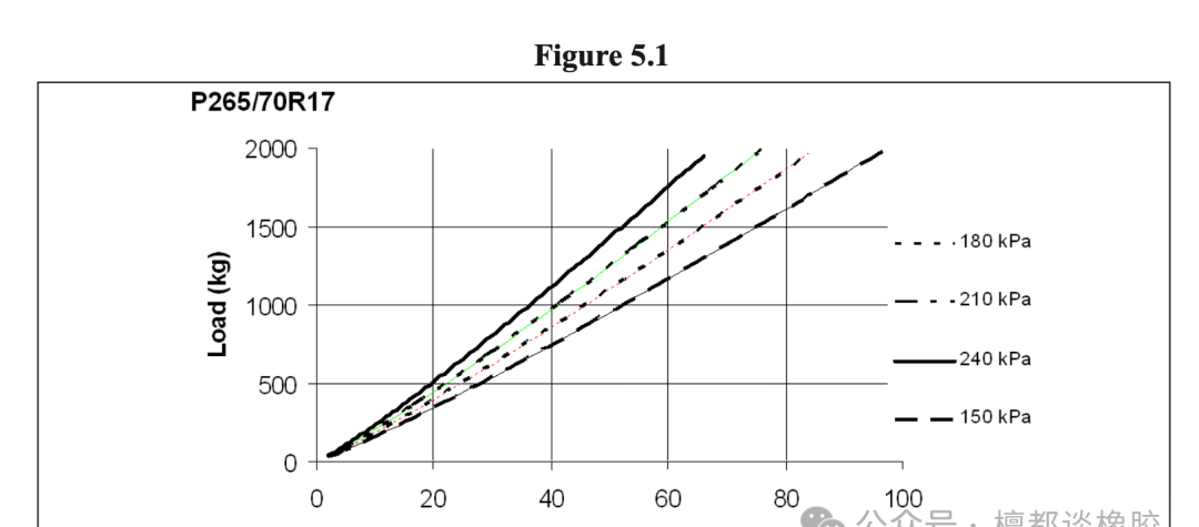
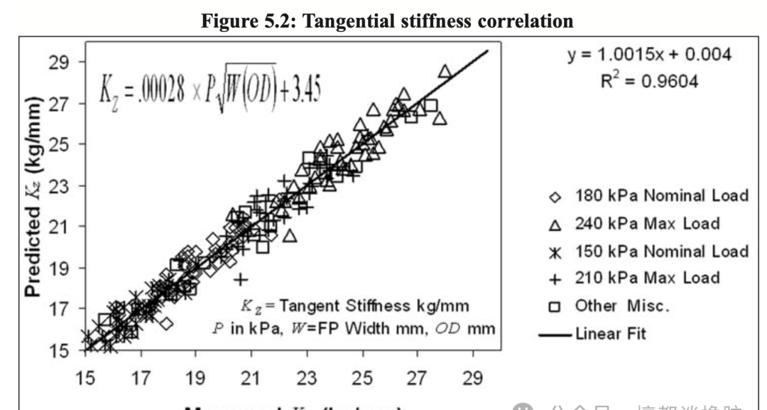
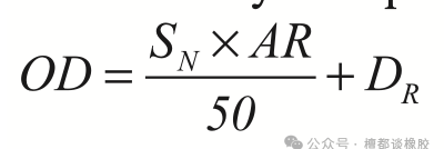
Industry consensus: at normal operating pressure, inflation pressure and tire dimensions (tread width, outer diameter) determine stiffness; tire structure itself contributes only 10–15%. Rhyne extended Koutny’s torus model to compute vertical stiffness directly. The tangent stiffness KZ is a function of pressure P, contact patch width W, and outer diameter OD:

Validated against 50 tires across 34 sizes with good correlation. The contact patch width W relates to nominal section width SN and aspect ratio AR via empirical coefficient a:
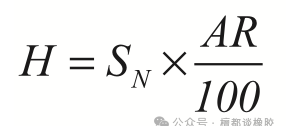
Table: Coefficient a by aspect ratio
| AR | 25 | 30 | 35 | 40 | 45 | 50 | 55 | 60 | 65 | 70 | 75 | 80 |
|---|---|---|---|---|---|---|---|---|---|---|---|---|
| a | 0.97 | 0.93 | 0.91 | 0.89 | 0.87 | 0.85 | 0.83 | 0.81 | 0.77 | 0.75 | 0.73 | 0.71 |
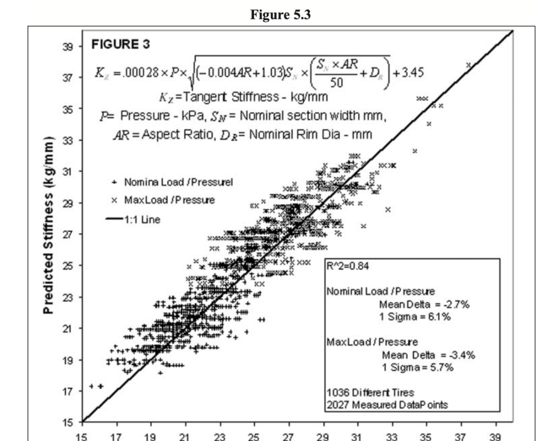
The stiffness model was validated against 2,027 test data points across 144 sizes and 1,000+ tires (rim 13–24″, section width 175–305 mm, aspect ratio 35–80), achieving R² = 0.84 between predicted and measured stiffness.
9. TRA Load Formula vs. Deflection
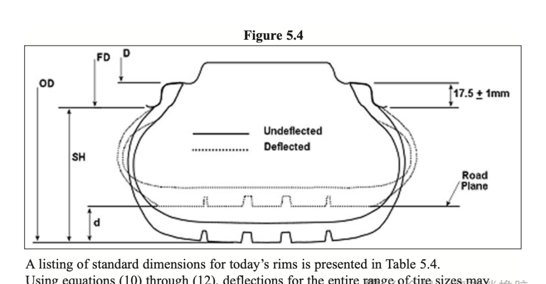
Tire engineers discuss load and pressure, but what really determines tire life is deflection. Greater deflection means more strain, more heat buildup, higher operating temperature, and greater rolling loss. The static deflection under any load-pressure combination is simply:

where d = deflection (mm), L = load (kg), KZ = tangent stiffness (kg/mm). For cross-size comparison, use relative deflection as a percentage of section height above the rim flange (SH).
10. Deflection Analysis
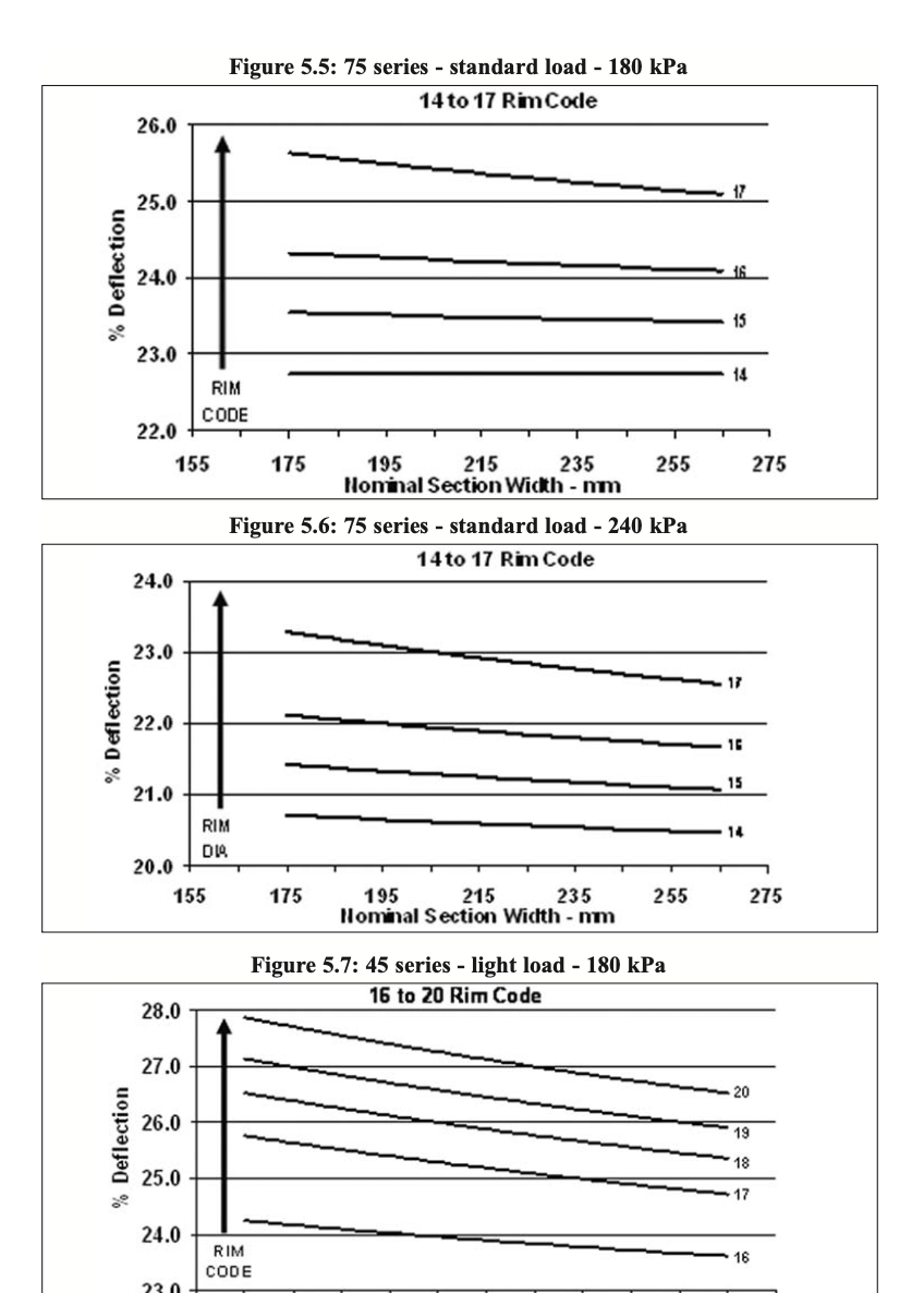
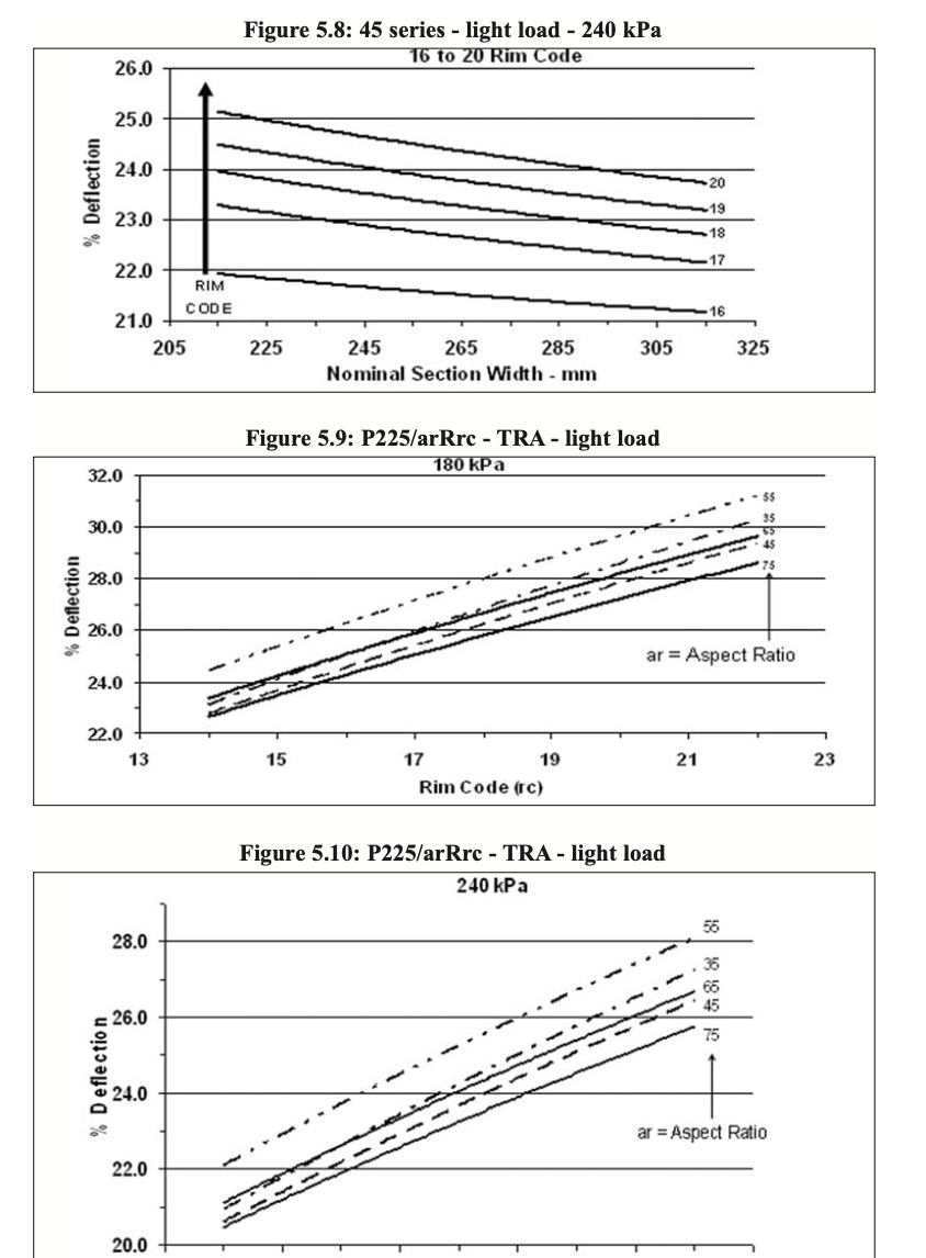
Applying the current TRA load formula across sizes reveals a systematic bias:
- 75-series tires at 180 and 240 kPa: as section width increases, relative deflection slightly decreases; as rim diameter increases, deflection rises significantly.
- 45-series low-profile tires: identical trend.
- Fixed section width, varying rim code: same aspect ratio geometry, only total diameter changes. Larger rim → higher relative deflection.
The current TRA formula penalizes large-rim tires: bigger rims require the tire to operate at higher deflection, accelerating fatigue and heat buildup.
11. Proposed Load Formula Based on Constant Relative Deflection
To eliminate the bias against low-profile, large-rim tires, a new formula is proposed based on constant relative deflection. Since rim flange height is a constant 17.5 mm on modern passenger rims, deflection can be expressed in terms of nominal section width and aspect ratio. Combining with the stiffness model yields a general load formula valid across all passenger tire sizes:

For maximum load calculations, use 240 kPa (the current P-metric standard-load reference pressure). Select the appropriate relative deflection percentage for the aspect ratio and compute load. Comparing the new formula with the existing TRA formula for 70-series tires confirms that the old formula underrates large-rim tires relative to the constant-deflection approach.

12. Future Work
The constant-deflection method needs further research to determine appropriate relative deflection targets for different tire categories. Whether 75-series and 30-series tires should share the same deflection threshold requires test data. The stiffness model also needs refinement for current and future tire designs. ISO has begun discussions on this approach.
Summary
The tire load formula has served for decades but needs revision for modern low-profile, large-rim tires. The proposed method based on constant relative deflection provides a physically grounded framework for evaluating current load ratings and developing future standards — covering everything from section width and aspect ratio to rim diameter and inflation pressure.


Leave a Reply
Want to join the discussion?Feel free to contribute!