Engineering Solid Tire Compound Design: Tread, Middle, and Base Compounds

Engineering solid tires are used in mines, construction sites, and other harsh environments where punctures, chunking, and blowouts are common. This article presents a three-compound formulation (tread / middle / base) using NR/SBR/BR blends with N326/N550/VN3 silica, meeting GB/T 10824-2008 for 12.00-20 solid tires.

Keywords: solid tire; engineering tire; tread compound; NR/SBR/BR; N326; silica; Si-69; anti-reversion agent; chunk resistance; cut resistance

Why Solid Tires?

In mining and construction environments, pneumatic tires suffer puncture damage, chunking, and bead blows — often leading to catastrophic failure. Engineering solid tires offer excellent puncture resistance and large abrasion volume. Because they are non-pneumatic, a severe puncture cannot cause a blowout, protecting vehicle operators.

Engineering vehicles operate in small-radius loops on rough terrain under heavy load. Beyond puncture damage, the tire generates significant compressive fatigue heat. Adding 20–30% compensated carbon black (relative to total CB) improves tear resistance and cut-growth resistance. When using silica, the bifunctional silane coupling agent Si-69 reacts with silica surface hydroxyl groups, converting silica from hydrophilic to hydrophobic and improving rubber compatibility.

Raw Materials and Formulation

Polymers: NR STR20, BR9000, SBR1502. Fillers: N326, N660 carbon black, VN3 silica. Chemicals: phenolic reinforcing resin, anti-tear resin SL-6903, silane Si-69, anti-reversion agent PK-900.

Three-Compound Formulation (phr)

Material Tread Middle Base
NR 80 65 70
SBR1502 10 — 30
BR9000 10 35 —
N326 37 48 —
N660 — — 60
Silica (VN3) 25 15 15
Zinc oxide 5 7 10
Stearic acid 2 2 2
RD antioxidant 2 2 2
4020 2 1.5 1.5
Si-69 coupling agent — 1.5 1.5
Anti-tear resin 2.5 — —
Sulfur 1.8 1.6 1.6
Accelerator 1.6 1.6 1.6
PK-900 anti-reversion 0.5 — 0.5

Mixing Process

Tread Compound — Low-Temperature Continuous Line (GK305)

Polymer + fine ingredients (anti-tear resin, ZnO, stearic acid, antioxidants, PK-900) → ram up 20s at 55 rpm → add silica, carbon black, Si-69 → ram down → dump at 135°C → slow to 25 rpm → ram down → dump at 150°C → sheet into rings → add pre-dispersed scorch retarder (2 min) → add pre-dispersed sulfur (2 min) → add accelerator (3 min) → sheet and cool.

Middle and Base Compounds — Two-Stage on F270

First stage (40 rpm): polymer + ZnO/stearic/antioxidants → ram 40s → add silica, CB, Si-69 → ram → 120°C ram up 10s → ram → dump at 145°C, rest 8h.

Second stage (20 rpm): masterbatch + sulfur/accelerator → ram 90s → ram up 10s → ram → dump at 105°C.

Key Results — Laboratory Recipe (small-scale)

Property Tread (60 min cure) Middle (60 min) Base (60 min)
M100% (MPa) 3.4 4.1 9.8
M300% (MPa) 11.8 15.6 —
Tensile strength (MPa) 24.8 21.9 14.6
Elongation at break (%) 532 501 183
Tear strength (kN/m) 101.2 50.2 41.3
Shore A hardness 70 65 88
Rebound (%) 50 55.8 32
Akron abrasion (cm³) 0.226 — —
Heat buildup — center (°C) 49.7 43.2 —
Heat buildup — bottom (°C) 10.6 12.0 —

Production-Scale Results (large batch)

Large-batch data matched small-batch results closely. Because low-temperature mixing was used, tensile strength was slightly better and dispersion grade improved (grade 5–6). Low-temperature mixing significantly reduces silica agglomeration in high-silica formulations.

Finished Tire Performance (12.00-20/8.0)

Property Tread — Measured Tread — GB/T 10824 Base — Measured Base — Standard
Tensile strength (MPa) 24.1 ≥18 14.1 ≥13
Elongation at break (%) 512 ≥450 179 —
Shore A hardness 69 67±5 89 85±5
Rebound (%) 49.6 — 32.5 —
Akron abrasion (cm³) 0.232 ≤0.6 — —

All properties exceed GB/T 10824-2008 requirements. Tensile strength and abrasion resistance far exceed the standard, extending service life in harsh mining/construction environments.

Formulation Rationale

  • N326 instead of N220 in the tread: higher tensile, elongation, and tear strength; lower heat buildup; better endurance and longer service life.
  • Si-69 coupling agent bridges silica surface to polymer, creating more filler-polymer bonds, reinforcing modulus and tensile strength, and improving abrasion.
  • Higher ZnO in middle compound (7 phr vs 5 in tread): reduces the temperature difference between surface and center during fatigue, extending tire life.
  • PK-900 anti-reversion agent in tread and base: prevents reversion during long cures (60–100 min) at 145°C.
  • Three-compound design (tread/middle/base): the middle compound provides low heat buildup and good buffering, lowering overall tire operating temperature vs. conventional two-compound solid tires.

Conclusion

The series includes 12.00-20, 11.00-20, and 10.00-20 small-to-medium engineering solid tires. They offer excellent abrasion resistance and superior chunk/cut resistance. The added middle compound layer (low heat buildup, good buffering) reduces overall operating temperature compared to standard solid tires, extending service life.

Tire Testing Technology: Endurance, High-Speed, Strength, and Road Performance

A tire is a multi-material composite structure (tread, carcass, bead) that must withstand radial loads, lateral forces, driving torque, and braking forces under harsh conditions. This article covers the full range of tire testing: laboratory drum tests (endurance, high-speed, strength, bead unseating) and road tests (dry/wet braking, handling, noise, coast-down).

Keywords: tire testing; endurance test; high-speed tire test; tire strength test; bead unseating; wet braking; dry handling; tire safety test

1. Tire Endurance Test

Concept: A tire-rim assembly inflated to specified pressure is pressed against a rotating drum (simulated road) at constant speed, with load increased stepwise over time. The test evaluates heat resistance and fatigue durability.

Test conditions:

  • PCR standard speed: 80 km/h; this comparison test used 120 km/h (50% more severe).
  • Load progression: Stage 1 = 100% (4h), Stage 2 = 110% (5h), Stage 3 = 115% (24h), Stage 4 = 125% (10h), Stage 5 = 135% (10h), continuing to 150% load.
  • Total cumulative test time: 120 hours.

Results (195/60R14 tires at 120 km/h):

Brand Manufacturer Speed (km/h) Time (h) Condition
Goodyear Dalian 120 120 No failure
Michelin Shenyang 120 120 No failure
Warrior Shanghai 120 120 No failure
Hankook Korea 120 120 No failure
Kumho Korea 120 120 No failure

All five brands passed with no failure after 120 hours at 120 km/h — demonstrating good durability.

2. Tire High-Speed Performance Test

Concept: The tire is loaded against the drum at constant load, and speed is increased stepwise until failure. This evaluates heat resistance and fatigue at speed.

Test load: PCR radial tire = max load × 0.8; light truck = max load × 0.88.

Speed progression (H-rated example):

Stage 1 2 3 4 5 6
Speed (km/h) 0–170 170 180 190 200 210+
Time (min) 10 10 10 10 10 10

Results:

Brand Passed Speed (km/h) Failure Speed (km/h) Failure Mode
Goodyear 260 270 Tread chunking (7.5 min at 270)
Michelin 260 270 Shoulder separation (5 min at 270)
Warrior 240 250 Shoulder separation (4.3 min at 250)
Hankook 240 250 Sidewall blowout (3 min at 250)
Kumho 210 220 Blowout (2 min at 220)

All five exceeded national standards. Goodyear and Michelin performed best (260 km/h passed); Kumho was weakest (failed at 220 km/h).

3. Tire Strength Test

Concept: A hemispherical steel probe of standard diameter is pressed into the tire tread at specified speed until failure (or reaching the rim). The minimum failure energy is recorded.

Method: Mount on standard rim, inflate, condition at 18–36°C for at least 3 hours, re-adjust pressure. Test at 5 equally spaced points around the circumference; press perpendicular to tread centerline on tread blocks (not grooves).

Failure energy formula: W = F × P / 2 (W in N·m, F in N, P in m penetration).

Results:

Brand Failure Energy (J) % of Standard Condition at Point 5
Goodyear 576 195.2% Not penetrated
Michelin 538 182.5% Penetrated
Warrior 482 163.2% Not penetrated
Hankook 529 179.2% Penetrated
Kumho 438 148.3% Penetrated

All exceeded the 140% standard. Goodyear was strongest; Kumho weakest.

4. Bead Unseating Resistance Test (Tubeless PCR)

Concept: A static lateral force is applied to push the bead inward off the rim flange. The maximum force required to unseat the bead is measured.

Why it matters: During cornering, centrifugal force can exceed the bead-rim seating force, causing the bead to displace inward and air pressure to drop rapidly — a serious safety hazard.

Results (average of 4 points):

Brand Unseating Force (N) Bead-Rim Condition
Goodyear 9,170 All 4 points sealed
Michelin 9,212 All 4 points sealed
Warrior 9,418 All 4 points sealed
Hankook 9,307 All 4 points sealed
Kumho 9,235 All 4 points sealed

All five brands exceeded national standard requirements with good safety margins.

5. Road Performance Tests: Big Three Comparison

A road test compared three premium tires on a BMW 325i (205/55 R16):

  • Michelin Energy MXV8 — comfort-focused, low rolling resistance (“XSE Green Technology”)
  • Goodyear Eagle NCT5 — sporty grip, “Tredcrown” technology, designed for Asian roads
  • Bridgestone Turanza GR-80 — new launch, “AQ Multicell” double-layer tread that maintains performance after wear

Dry Braking (100–0 km/h)

Tire Cold (35°C tread) Hot (50°C tread)
Bridgestone 42.7 m (best) 41.9 m (best)
Michelin 44.5 m 43.7 m
Goodyear 48.1 m 45.2 m

Warm tires brake shorter — tire temperature matters for grip.

Dry Handling (Slalom)

Tire Average Slalom Speed
Goodyear 62.1 km/h (best)
Bridgestone 60.5 km/h
Michelin 60.5 km/h

Goodyear’s sporty nature showed clearly in lateral grip.

Noise Test (80 km/h exterior)

Tire Noise Level
Michelin 75.1 dB (quietest)
Bridgestone 75.9 dB
Goodyear 77.2 dB

Coast-Down (Rolling Resistance)

Coasting in neutral from 20 km/h to stop:

Tire Coast-Down Distance
Goodyear 269 m (longest = lowest RR)
Michelin 227 m
Bridgestone 200 m

Wet Braking (60–0 km/h on water film)

Tire Wet Braking Distance
Bridgestone 14.6 m (best)
Michelin 14.7 m
Goodyear 15.0 m

Wet Cornering

Tire Wet Cornering Speed
Goodyear 55 km/h (best)
Michelin 50 km/h
Bridgestone 50 km/h

Summary

No single tire won every test — each had its strengths:

  • Michelin MXV8: Quietest ride, best comfort, good wet braking — but longest dry braking distance.
  • Goodyear NCT5: Best dry/wet handling and slalom, lowest rolling resistance — but noisiest and longest dry braking.
  • Bridgestone GR-80: Best dry and wet braking, balanced overall — but shortest coast-down (higher RR).

High-speed testing is the most demanding laboratory test — endurance, strength, and bead unseating are relatively easy to pass, but high-speed performance exposes structural weaknesses. Tire selection should match vehicle and use case: “fit” matters more than simply “best.”

Source: Adapted from “Tire Testing Technology,” by Tan Du Talks Rubber.

Natural Rubber Compound Formulation Design: A Practical Guide

Natural rubber (NR) is an unsaturated, crystallizable diene rubber with excellent elasticity, high mechanical strength, and superior processing characteristics. It is the oldest and most widely used rubber type. This guide covers the four core formulation systems: vulcanization, reinforcement/filling, protection, and plasticization.

Keywords: natural rubber; NR; compound formulation; vulcanization system; sulfur cure; carbon black; antioxidant; plasticizer; rubber recipe design

1. Vulcanization System

Curing agents suitable for natural rubber include sulfur, selenium, tellurium; sulfur donors; organic peroxides; ester-type; and quinone-type curing systems. The choice depends on the required product properties.

Sulfur vulcanization systems vary by the ratio of accelerator to sulfur, producing three characteristic systems:

Conventional Sulfur Cure (High Sulfur / Low Accelerator)

Uses high sulfur and low accelerator. Crosslinks are predominantly polysulfidic bonds. The uncured compound has good general physical-mechanical properties: high strength, good elasticity, high abrasion resistance, and low cost. However, heat resistance and aging resistance are poor, and reversion during cure is significant. Because NR has high unsaturation, sulfur loading can be higher than in synthetic rubber — typically 2–3 phr (commonly 1.75–2.75 phr) for soft rubber products. Accelerator loading is below 1 phr.

Common accelerators: M, DM, CZ, NOBS, D, TT. They can be used alone or in combinations such as DM, D/TS, D/DM, M/H, M/TT, M/TS, CZ/TT, DM/D/H, DM/M/TT, DM/TT, CZ/DM, NOBS/DM.

Semi-Efficient Cure (semi-EV)

Intermediate between conventional and efficient cure. Uses medium sulfur loading (1–1.7 phr) with accelerator. Crosslinks contain both polysulfidic and mono/disulfidic bonds. The vulcanizate combines heat resistance, fatigue resistance, and reversion resistance — widely used. Typical recipes: S/NS (1.5/1.5), S/NS/DTDM (1.5/0.6/0.6).

Efficient Cure (EV)

Low sulfur / high accelerator ratio, producing mainly mono- and disulfidic crosslinks with excellent heat aging and reversion resistance, but lower tensile strength and dynamic fatigue resistance.

Effect of Sulfur Loading on NR Vulcanizate Properties

Sulfur (phr) 1.0 1.5 2.0 2.5 3.0 3.5 4.0
M300% (MPa) 6.4 7.3 8.0 9.1 10.0 11.5 12.8
Tensile strength (MPa) 26.0 28.3 29.6 31.5 31.1 31.1 31.6
Elongation at break (%) 670 672 660 660 670 670 660
Permanent set (%) 23 29 34 34 42 42 46
Shore A hardness 57 60 64 64 68 68 69

Accelerator: DM 0.5 phr + M 0.5 phr.

Other Cure Systems

  • Ester-type (urethane) cure: Addition products of diisocyanates (TDI, MDI) and p-nitrosophenol. Provides good reversion resistance, heat resistance, and aging resistance. Improves adhesion to cords, fabrics, and steel.
  • Maleimide cure: High-temperature cure system with excellent reversion resistance, thermal stability, low compression set, and good glass-fiber adhesion. Most effective: N,N’-m-phenylene dimaleimide and 4,4′-dithiodiphenyl maleimide.
  • Organic peroxide cure: DCP (dicumyl peroxide) at 2–4 phr forms C-C crosslinks. Provides excellent thermal stability, heat aging, low creep, low compression set, and good dynamic properties. Fast cure speed, high crosslink efficiency.

Sulfur cures typically use zinc oxide 2–5 phr and stearic acid 1–3 phr as activators.

2. Reinforcement and Filling System

Porous powder quartz (natural amorphous silica) improves physical properties with high fineness, high activity, and low specific gravity. It can partially replace carbon black and silica to reduce cost.

Carbon Black Selection

Requirement Recommended Carbon Black
High abrasion resistance N110 (SAF), N220 (ISAF), N330 (HAF)
High tear resistance Channel black best
Lower strength, high elasticity, good processing N550 (FEF), N660 (GPF), N770 (SRF)

When selecting carbon black, consider particle size, structure, surface activity, and pH. pH affects cure speed — adjust the cure system accordingly. For furnace blacks, use delayed-action accelerators in moderate dosage.

Light-Colored Compounds

For light or bright-colored products, use precipitated silica, highly dispersible silica, or ultra-fine porous quartz. When using precipitated silica, add organo-activators such as diethylene glycol (DEG), glycerin, ethanolamine, or polyvinyl alcohol at 5–10% of silica loading to adjust cure speed.

For maximum tensile strength, filler loading of 40–45 phr is optimal; excessive loading reduces strength. For low-strength, low-cost products, add clay or CaCO3 to reduce rubber content.

3. Protection System

Because NR is unsaturated, it readily reacts with oxygen and ozone, causing aging. Heat, light, flexing, and metal ions (manganese, copper) accelerate degradation. Antioxidants must be selected based on actual service conditions:

  • General antioxidants: D, A, DNP, 4010, 4010NA, AW, MB, SP, SP-C, RD
  • Can be used alone or in combinations
  • For light-colored products, choose non-staining antioxidants

4. Plasticizing / Softening System

Physical Plasticizers

Used for processing benefits: tackiness, softness, easier mixing/calendering/extrusion, and hardness adjustment. Common types: pine tar and solid coumarone-indene resin at 4–5 phr; petroleum-based softeners at 5–15 phr.

Chemical Plasticizers (Peptizers)

Smoked sheet and crepe natural rubber have high Mooney viscosity, making mastication difficult. Traditional addition of accelerators M and DM is not effective. Chemical peptizers improve mastication efficiency and shorten cycle time. Common peptizers for NR: SJ-103 (works on both open mills and internal mixers) and 12-I (internal mixer only), at 0.1–0.3 phr.

Summary

Natural rubber formulation design balances four systems:

  1. Vulcanization: Choose conventional / semi-EV / EV based on heat aging vs. strength trade-off; sulfur loading directly modulates M300, hardness, and permanent set.
  2. Reinforcement: Match carbon black grade to abrasion/tear/elasticity needs; use silica for light colors; 40–45 phr for maximum strength.
  3. Protection: Select antioxidants based on aging environment; use non-staining grades for light colors.
  4. Plasticization: Physical softeners for processing; chemical peptizers for high-Mooney NR mastication.

Green Tire Pallet Conveyor System: Automated Transport for PCR/LTR Tire Plants

A green tire pallet conveyor system is a fully automated production-line solution for transporting uncured (green) tires between the tire building machine and the curing press in PCR passenger and LTR light truck tire plants. Each green tire stays on its own dedicated pallet throughout the process, enabling damage-free gentle transport and 100% individual track-and-trace.

Keywords: green tire; pallet conveyor; tire plant automation; tire building; curing press; WMS; MES; RFID; green tire storage

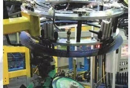
Green tire pallet conveyor 1

System Overview

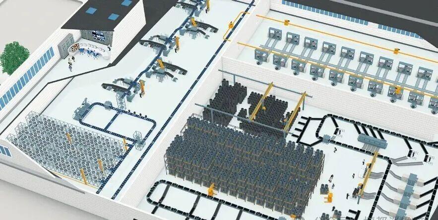
The system integrates conveying, sorting, and buffer storage into one automated line. After building, the green tire is loaded directly onto a dedicated transport/storage pallet — either manually or by a robot from the building machine. The tire remains fixed on its pallet through conveying, buffering, and curing loading. This eliminates unnecessary gripping and flipping, enabling damage-free gentle transport and precise per-unit traceability.

Key Features

  • Fully integrated automation for all green tire sizes
  • Complete transport from tire building machine to curing press with minimal tire handling/gripping
  • RFID technology tracks every tire individually through the entire production flow
  • Quick installation for new plants or retrofitting existing lines; compact footprint

Core Principle: Minimize Gripping and Flipping

The central logic: each green tire is loaded onto its dedicated pallet at the building machine, transported to buffer storage, and held there until the curing press requests it. The tire never leaves the pallet between building and curing. This contactless gentle transport eliminates extra gripping and flipping operations that could distort the green tire, dramatically improving line efficiency.

The system uses standardized modular components that can be combined on demand for high flexibility. The equipment has a small footprint, high vertical integration, very low energy consumption, low spare-parts requirements, and low maintenance costs — achieving the lowest operational expense (OPEX) in the industry.

Control and Monitoring

A Warehouse Management System (WMS) tracks every pallet throughout the process and schedules logistics, with bidirectional data exchange to MES and ERP systems. This enables full-process monitoring, scheduling, and optimization of the entire line.

Pallet and Tire Adaptation

The system uses dedicated conical pallets compatible with multiple tire sizes. The conical pallet contacts the tire bead over a very small area, preventing bead deformation and improving manufacturing flexibility and finished quality. The pallet contact surface can be lined with various materials to reduce rubber sticking.

Integration with Tire Building Machines

The pallet system connects directly to the building process. Green tires stay on pallets without repeated gripping, preventing deformation. Tires are loaded directly from the building machine onto pallets without extra lifting or repositioning. Older low-output single-stage building machines can use manual pallet loading; newer high-output machines can integrate automatic loading modules.

Optional Isolant Spraying Integration

An automatic isolant (release agent) spraying system can be integrated before or after pallet buffer entry as an optional feature.

Integrated Green Tire Buffer Storage

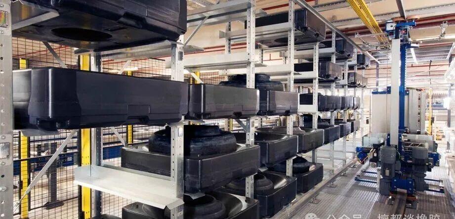
Independent pallet storage of green tires is the core function. The pallet buffer warehouse provides short- and long-term capacity buffering between building and curing. Sprayed green tires can rest and dry in the storage area. The warehouse uses Miniload (lightweight box stacker) technology: any green tire can be retrieved at any time, following FIFO (first-in-first-out) — the earliest tire of a given size is served first. In case of production anomalies, a specific tire can be quickly and precisely retrieved.

The storage unit consists of rail-mounted stacker cranes, lightweight pickers, conveyors, and steel racks. A single warehouse has 500–1,500 pallet locations depending on line capacity; multiple warehouse units can be combined to achieve optimal buffer capacity in limited space.

Green tire pallet conveyor 2

Automated Curing Press Loading

Curing is the core high-cost process in tire manufacturing. Wrong green tire loading wastes energy and raw materials and can damage the curing press. The automated pallet conveyor delivers the green tire (on its pallet) directly to the curing press, fully eliminating extra gripping and flipping. The system also includes a tread splice positioning correction unit that aligns the tire joint before loading, avoiding mold defects.

Manual Workstation

A dedicated manual workstation allows operators to load/unload pallets and perform manual inspection. Tires that cannot be identified by the automatic system (barcode read failure) are diverted to the manual station, where operators use handheld scanners to enter tire data.

Standard Modular Components

Line Interface Modules

  • Tire building machine interface
  • Automatic isolant spraying system
  • Curing press loading conveyor

Conveying Modules

  • Straight conveyor sections
  • Curved sections
  • Acceleration/deceleration sections
  • Vertical lifts / circulation elevators

Sorting Modules

    li>Diverters
  • Mergers
  • 90° transfer cars
  • Vertical sorting units

Storage Modules

  • Pallet Miniload warehouse
  • Through-flow pallet buffer line

Green tire pallet conveyor 3

Full-Process Traceability

The system achieves 100% precise tracking of all pallets. The location and data of any individual green tire can be queried at any production step. Operators can check the real-time position of any pallet; the system has preset tracking points that automatically report data as pallets pass. Pallets can be stopped or started at any time without losing trace information.

Technical Parameters

Parameter Value
Conveyor speed 2.3 m/s (6.6 ft/s)
Line throughput 2,500 pallets/hour
Tire inner diameter (bead) 330–660 mm (13–24 inches)
Tire outer diameter 450–875 mm (18–35 inches)
Max green tire weight 35 kg (77 lb)
Pallet size 900 × 900 mm

Rubber Mixing in an Internal Mixer: Step-by-Step Operation Guide

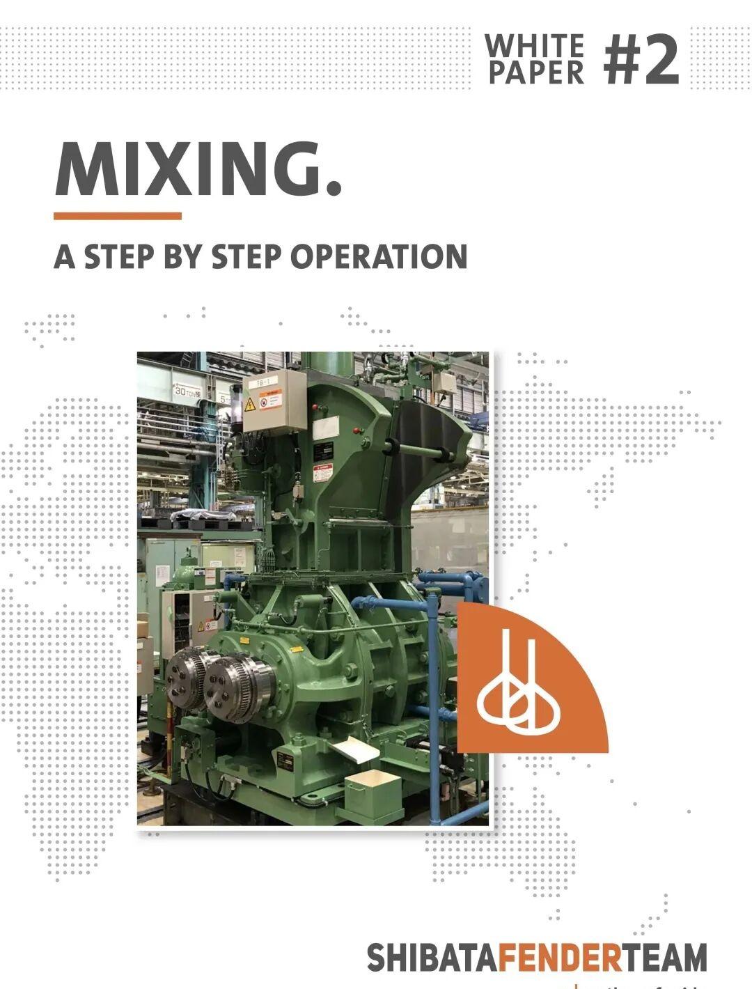
This article is based on the Shibata Fender Team (SFT) White Paper Series Part II — Mixing. It walks through the complete two-stage rubber compounding process: mastication, masterbatch production, and finalization, with the equipment and operational principles behind each step.

Keywords: rubber mixing; internal mixer; banbury; mastication; masterbatch; finalization; two-stage mixing; rubber compounding; fender manufacturing

Executive Summary

Fender manufacturing, like all rubber product manufacturing, relies heavily on practical knowledge and experience. The complex interaction between raw material composition, mixing equipment, and process parameters makes uniform high-quality output difficult to achieve without deep expertise.

Current international standards (PIANC 2002, ASTM D2000, EAU 2004, R20 2.0-11 (2012), or BS6349 (2014)) only define the final physical properties of a fender — they do not specify the chemicals used or the mixing equipment. The manufacturer’s performance and process know-how remain the defining factors.

This white paper outlines the individual steps of rubber mixing to show how a high-quality fender (or tire, or any rubber product) is built up through controlled processing.

Mixing process page 1

The SFT White Paper Series

The four-part series covers the entire process from rubber compounding to final product testing:

  • #1 Compounding — raw materials and their correlation to final properties
  • #2 Mixing — the mixing process and equipment (this article)
  • #3 Curing — manufacturing and vulcanization
  • #4 Testing — final product testing and quality verification

Mixing process page 2

With its White Paper Series, SFT advocates transparency in fender production to ensure quality standards driven by a commitment to high-performance products.

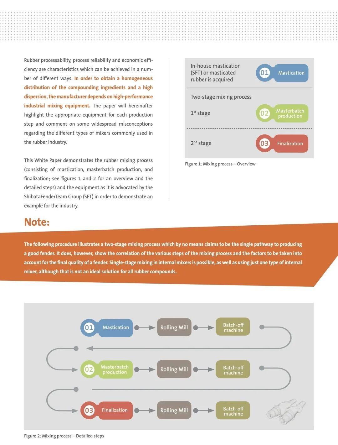
The Two-Stage Mixing Process

Since mixing is essential to rubber product quality, this part focuses on the individual phases: mastication → masterbatch production → finalization.

Rubber processability, reliability, and economic efficiency require high-performance industrial mixing equipment. To achieve homogeneous distribution of compounding ingredients and high dispersion, the manufacturer depends on well-matched equipment choices for each production step.

Mixing process page 3

Note: The following procedure illustrates a two-stage mixing process. Single-stage mixing in an internal mixer is also possible, but not ideal for all compounds. Two-stage mixing separates the high-energy dispersion work (masterbatch) from the low-temperature vulcanization-incorporation work (finalization), preventing premature cure.

Mixing process page 4

A. Compounding Ingredients — Fundamental Choices

A well-considered chemical composition is the cornerstone of a high-quality rubber product. The selection of raw rubber is particularly important because natural rubber (NR) as a natural product varies in viscosity due to molecular weight and uneven molecular distribution.

Mixing process page 5

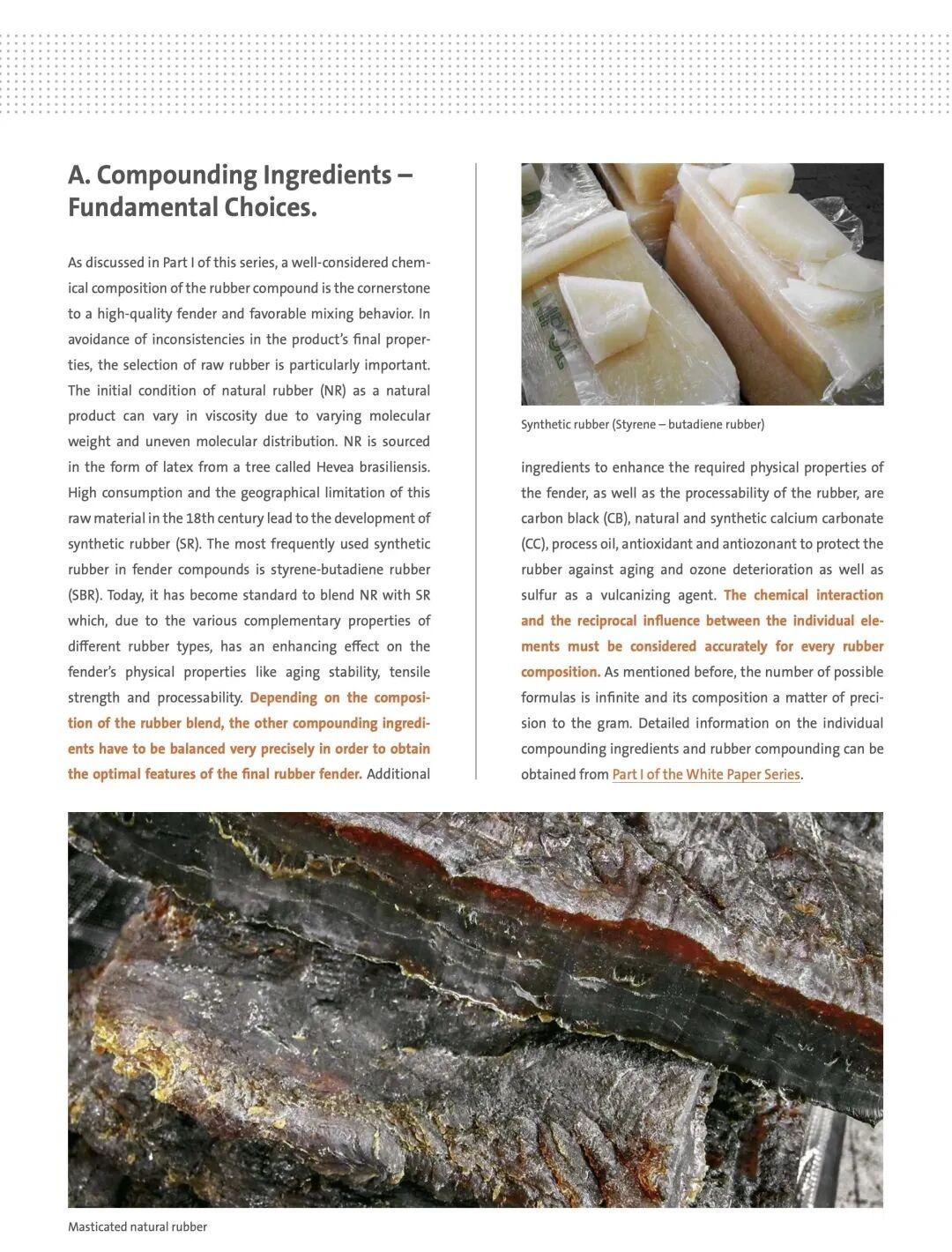
Natural Rubber (NR) is sourced from Hevea brasiliensis. High consumption and geographical limitations led to the development of synthetic rubber (SR). The most common synthetic rubber in fender compounds is styrene-butadiene rubber (SBR). Today it is standard to blend NR with SR — the complementary properties of different rubber types enhance aging stability, tensile strength, and processability.

Other ingredients — carbon black (CB), natural and synthetic calcium carbonate (CC), process oil, antioxidant, antiozonant, and sulfur as vulcanizing agent — must be balanced precisely depending on the rubber blend composition. The chemical interaction between individual elements must be accurately controlled. Formulation precision is measured to the gram.

Mixing process page 6

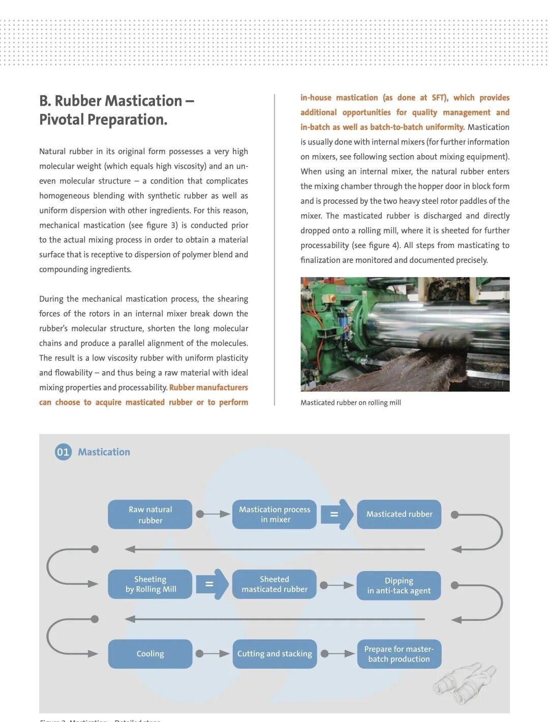
B. Rubber Mastication — Pivotal Preparation

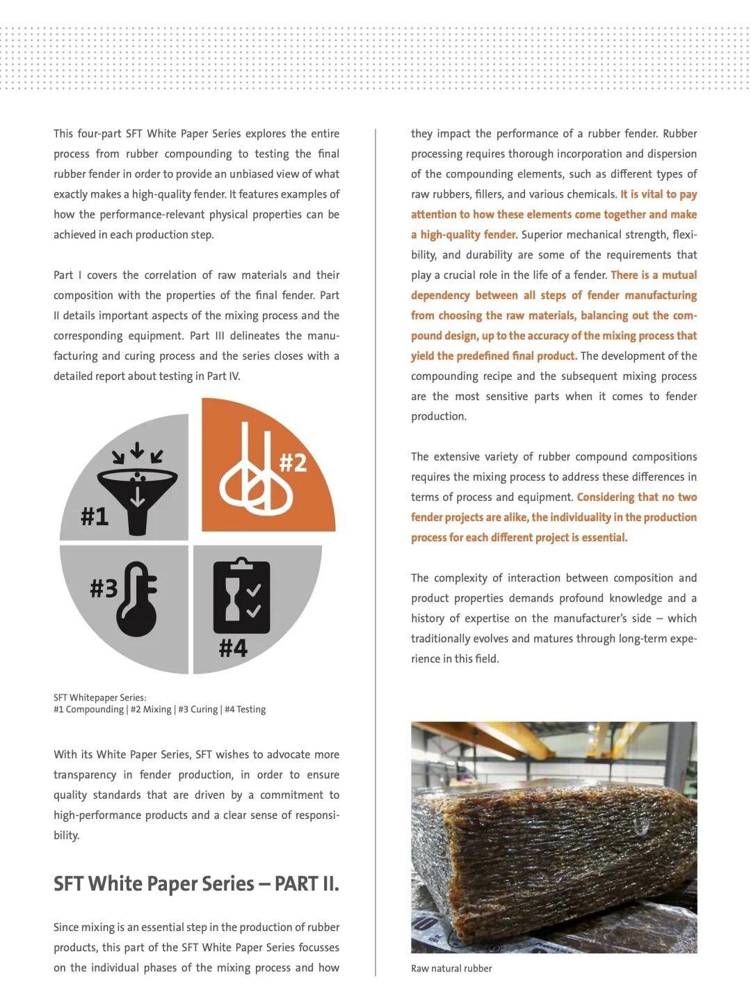
Mastication is the mechanical breakdown of high-molecular-weight natural rubber into a more processable, flowable state. This is done either in-house or purchased pre-masticated. The goal is to reduce Mooney viscosity so that subsequent mixing steps can incorporate fillers and chemicals uniformly.

Mixing process page 7

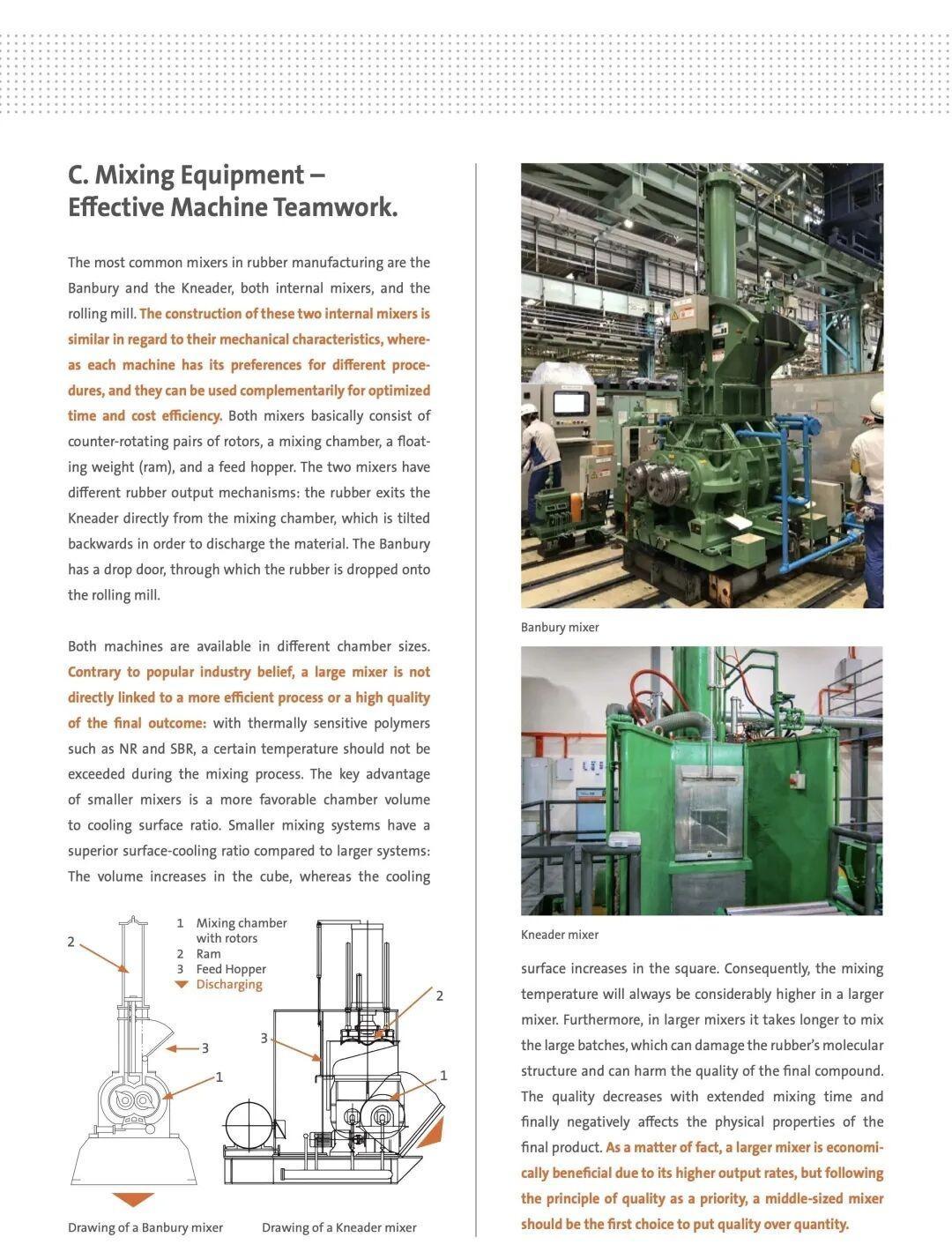
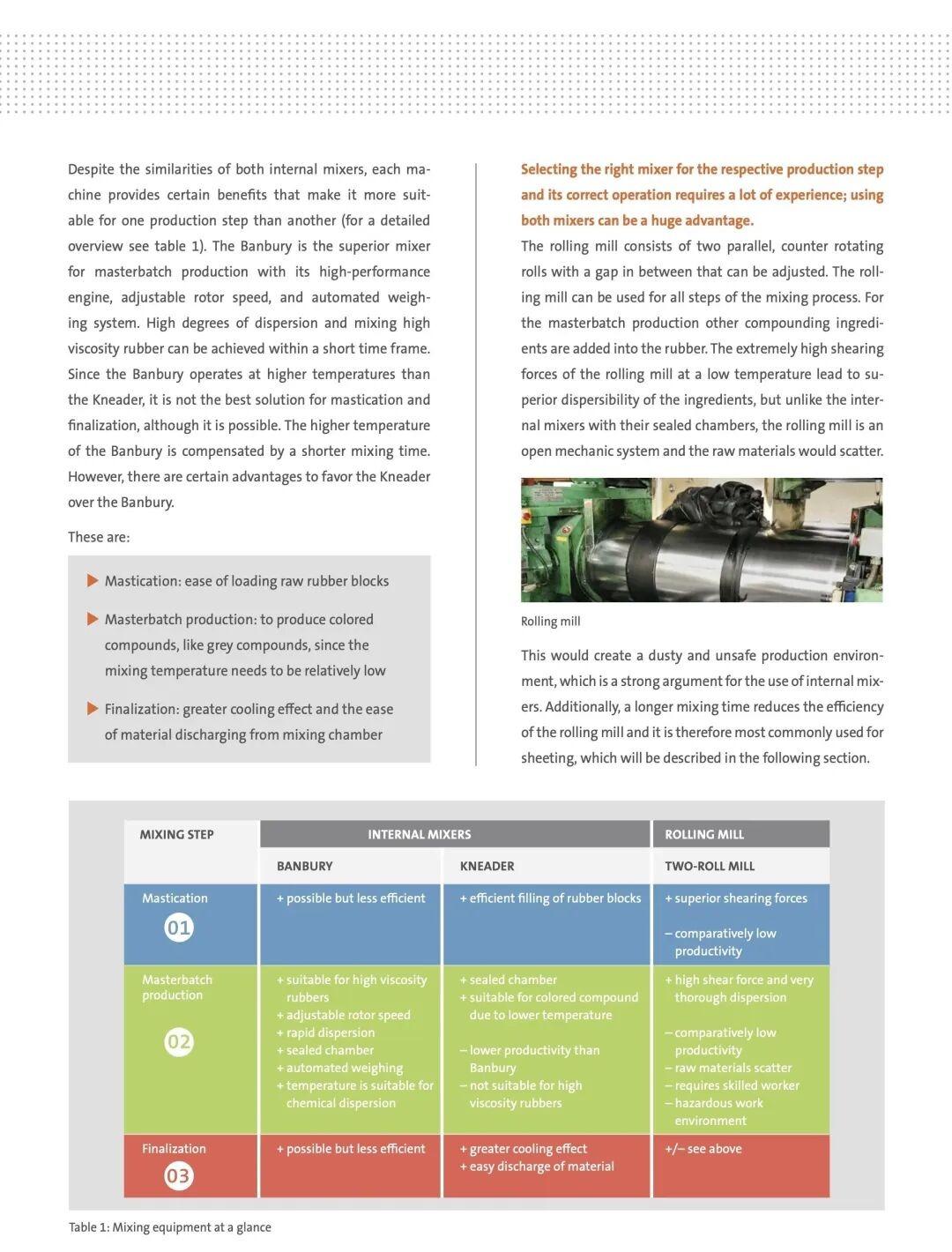
C. Mixing Equipment — Effective Machine Teamwork

The internal mixer (Banbury-type) is the workhorse. High-shear rotors generate the dispersion needed to break up filler agglomerates and distribute them throughout the rubber matrix. Cooling of the chamber, ram pressure, rotor speed, and dump temperature are all recipe-controlled.

Mixing process page 8

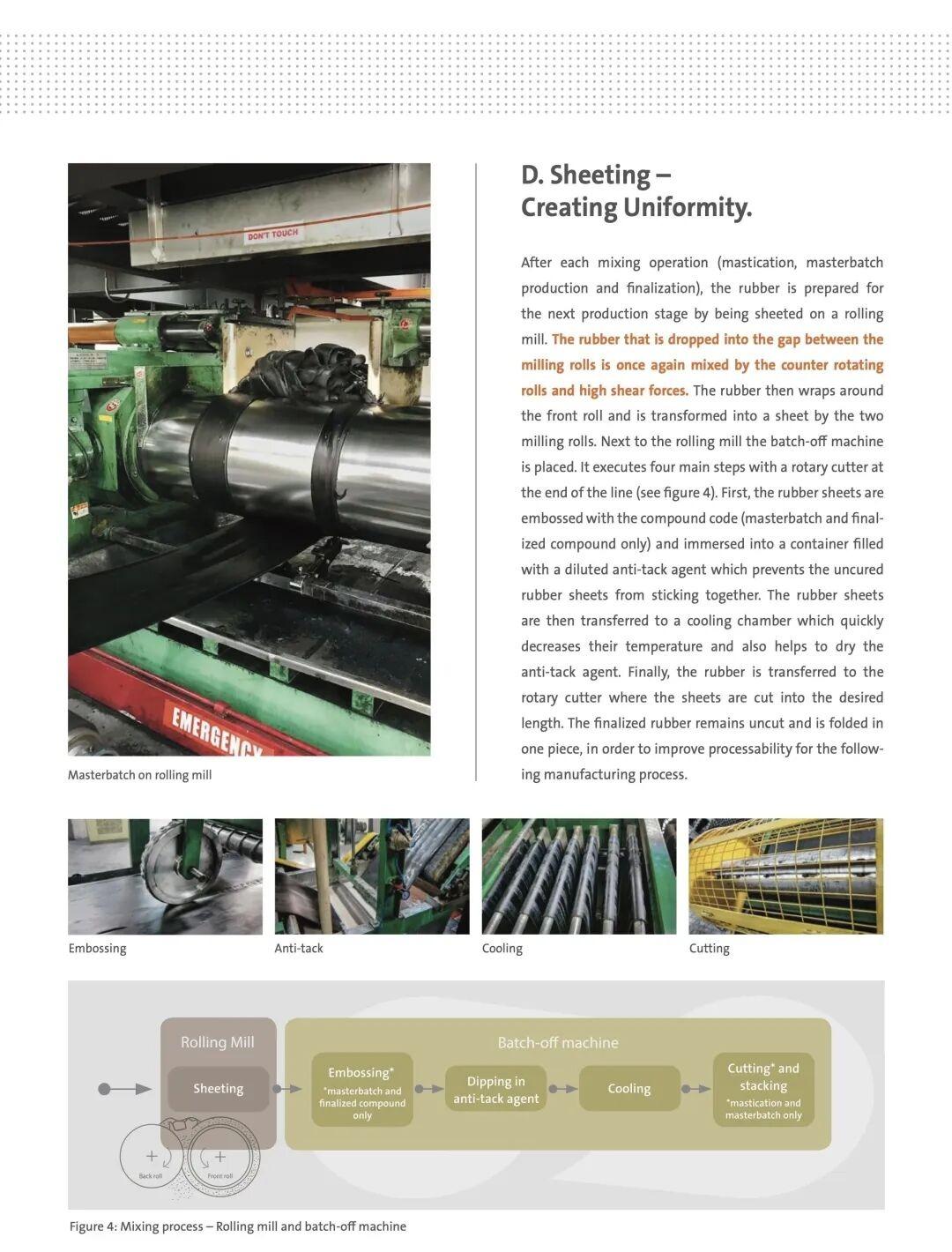
D. Sheeting — Creating Uniformity

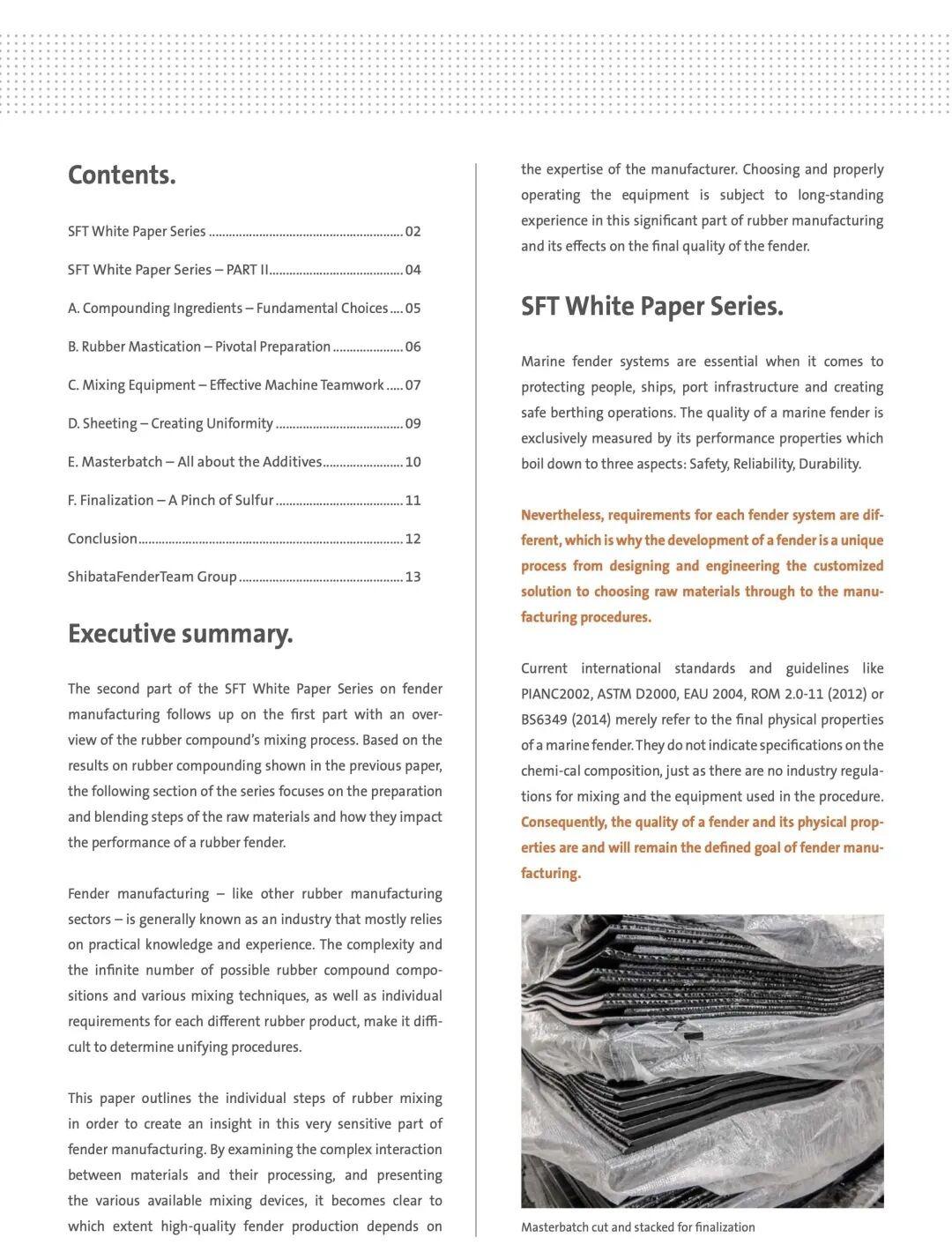
After each mixing stage, the batch is dropped onto a rolling mill (open mill), sheeted out, and cooled on a batch-off conveyor. This equalizes temperature, forms a handleable slab, and allows inspection. The two-stage process means the masterbatch is sheeted, cooled, and then re-loaded for the finalization stage where sulfur and accelerators are added at lower temperature.

Mixing process page 9

E. Masterbatch — All About the Additives (1st Stage)

The first (high-temperature) mixing stage incorporates all ingredients except curatives: base polymers, carbon black/filler, oil, antioxidants, activators (zinc oxide, stearic acid). High temperature (typically 140–160°C) drives the filler-rubber interaction and dispersion. The masterbatch is then dropped, sheeted, and cooled.

Mixing process page 1

0

F. Finalization — A Pinch of Sulfur (2nd Stage)

The second (low-temperature) stage re-mills the cooled masterbatch and adds sulfur and accelerators at temperatures below ~110°C to prevent scorch. After finalization, the compound is sheeted, cooled, and ready for curing.

Mixing process page 1

1

Mixing process page 1

2

Mixing process page 1

3

Mixing process page 1

4

Key Takeaways

  1. Two-stage mixing is the industry standard for quality compounds: masterbatch handles dispersion at high temperature; finalization adds curatives at low temperature.
  2. Mastication reduces NR viscosity for consistent processing.
  3. Formulation precision matters to the gram — filler-rubber interactions define the final properties.
  4. Equipment and process experience — not just raw material choice — determines final product quality. Standards define the output, not the process.
  5. Every step (mastication → masterbatch → sheeting → finalization → sheeting) feeds into the next; skipping or shortening any step degrades dispersion and consistency.

INTEREUROPEAN Tire Building Machines: Uni-Stage, COMBI, and Traditional TBM Overview

This article introduces INTEREUROPEAN’s complete tire and rubber machinery lineup: Uni-Stage single-stage tire building machines, COMBI combined-stage TBMs, traditional first/second-stage TBMs, bead apexing lines, bias cutters, slitter lines, and air spring production equipment.

Keywords: tire building machine; TBM; Uni-Stage; green tire; bead apex; tire manufacturing equipment; COMBI TBM; air spring

1. Uni-Stage TBM (Single-Stage Tire Building Machine)

The next-generation fully automatic single-stage tire assembly machine uses Uni-Stage process technology, globally recognized and nominated for the 2015 Tire Technology International Innovation Excellence Award.
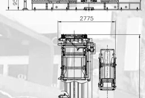
Uni-Stage TBM general assembly drawing

Key Configuration Features

  1. All rubber semi-components have active guiding/correction systems, automatic cutting and stitching. Flat-drum tire assembly process. Advanced HMI touchscreen control with recipe management and self-diagnostics.
  2. Robots mount beads into bead lock positioning; transfer rings automatically unload green tires from the Uni-Stage drum.
  3. Customizable: 1-ply / 2-ply carcass, steel/fiber chafer; in-line or off-line inner liner + sidewall pre-assembly; tread from roll or pre-cut lengths; independent sidewall application.
  4. Uni-Stage drums supplied by INTEREUROPEAN (bladder-type or mechanical turn-up) or adapted to customer’s existing standard drums.
  5. High-config model with double belt drum + double Uni-Stage drum achieves 30-second cycle time per tire.
  6. Optional off-line inner liner + sidewall pre-assembly line to reduce costs and increase output.

In fully automatic mode, cycle time ranges 30–35 seconds per tire depending on drum type and material feeding configuration.

Machine Body

  • Inner liner and sidewalls can be applied separately on the building drum for maximum recipe design freedom. Independent sidewall feed with ultrasonic cutting and electronic guiding; adds only 5 seconds to cycle time.
  • Bead + isolator ring cassettes come from the company’s proven apexing line. One apexing line serves 2 Uni-Stage machines as standard supply.
  • Same robot places beads onto automatic bead lock mechanism during the work cycle.
  • Carcass components (inner liner + sidewall composite, 1st ply, 2nd ply) are centered by active guiding systems, cut to length, and applied to the Uni-Stage drum.
  • Inner liner + sidewall composite uses special ultrasonic cutting with adjustable angle for minimal-angle skew cuts to increase joint contact area and avoid air entrapment. Multiple roller discs exhaust air during application.
  • Throughout assembly, the carcass remains on the same Uni-Stage drum. After turn-up, the drum moves to pre-shaping position; the transfer ring picks up the belt-tread assembly from the belt drum and applies it.

Belt & Tread Assembly Unit

Belt and tread assemblies are built in two steps on independent belt drums mounted on a rotating turret:

  • New-generation belt feeder: magnetic conveyor splices belt ends from below; high-definition cameras provide active belt guiding; multiple electronic systems verify length for uniform circumference distribution.
  • After belt application, a high-speed winding head immediately applies nylon cap ply spirals with tension control; all winding patterns are programmable in recipes.
  • Tread is applied directly from roll; on-drum ultrasonic knife cuts the tread (7/8 cut) with near-invisible splice. Adjustable skew angles maximize splice contact area. Pressure-adjustable multiple roller discs stitch the tread; active guiding centers the tread before application.
  • After tread application, the transfer ring carries the belt-tread assembly to the pre-shaped carcass; final shaping, dynamic rolling, and green tire unloading complete the cycle.

Fully Automatic Material Feed System

Each unwind station has two removable slide carriages. While the machine runs, operators can change rolls outside the station; switching carriages automatically splices material inside, minimizing downtime.

The modular control system uses Allen-Bradley or Siemens PLC with touchscreen HMI, recipe management, full alarm handling, and production statistics. Optional chafer, gum strip, and nylon cap ply feeds; various drum sizes; motor-adjustable belt drums; full range of transfer rings. All key process parameters are electrically recipe-driven: conveyor angle follows drum diameter, centering follows material width, rolling follows tire size — minimizing changeover time while maintaining flexibility and capacity.

Standard Configuration

  • a. Rotary main frame with 2 Uni-Stage drums
  • b. Component splice monitoring system
  • c. Rotating turret with double belt drums covering all diameter ranges
  • d. Mobile transfer ring with multi-segment sectors for full diameter range
  • e. 3 laser positioning marking systems
  • f. Multi-disc stitching rollers for exhaust
  • g. Automatic bead lock ring; automatic bead loading robot
  • h. Fully automatic carcass component feeder (2-ply capability, 4 unwind stations, active guiding, automatic length cutting, inner liner+sidewall pre-assembly, splice/wrinkle detection sensors, roll-present sensors, rigid vibration-damping frame)
  • i. Fully automatic belt-tread component feeder (1st/2nd belt feeders with bottom splicing, double unwind each, active guiding, length verification, nylon cap winder with tension control, large accumulator, tread feeder with double unwind, multi-stage active guiding, on-drum ultrasonic tread cutting up to 15° skew, pressure-adjustable tread stitching, deformation/splice sensors)
  • j. Green tire dynamic rolling device (all parameters recipe-driven; compatible with TOS/SOT structures)

ITAC Integrated Tire Assembly Unit (2.5 Million Tires/Year)
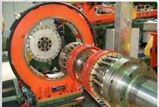
Uni-Stage TBM on-site view 1
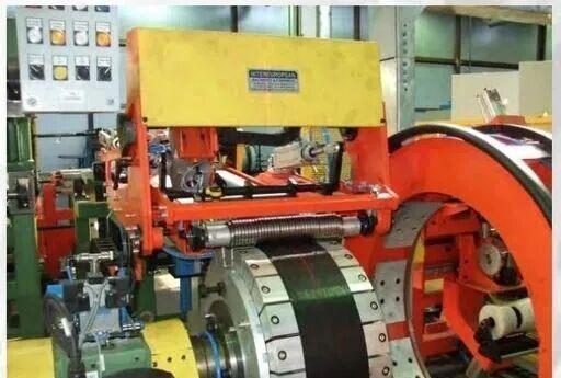

Uni-Stage TBM on-site view 2

The ITAC unit consists of:

  • 4 fully automatic tire building machines
  • 2 bead apexing lines
  • 1 bead winding line

Capacity: 8,000 green tires/day, 2.5 million tires/year; can produce 4 different tire sizes simultaneously. Staffing: 6 operators total (1 per building machine, 1 shared between two apexing lines, 1 for bead winding).

Beads are wound in the dedicated in-unit bead line (square or hexagonal cross-section). Beads are automatically unloaded from the drum into cassettes, conveyed to the two apexing lines for apex extrusion and application. After apex application, robots load beads onto mobile carts separated by plastic isolator rings. Carts automatically transport to the 4 building machines. Buffer carts at each building machine inlet ensure 24-hour uninterrupted production. Each apexing line changes size every 12 hours or every 4,000 beads, and can supply two sizes to two machines simultaneously.

Bead manufacturing, apexing, and tire assembly are fully inspected by cameras and laser light curtains at every step. Automatic size changeover minimizes downtime. Four independent machines can each dedicate to specific sizes, only changing within the same bead diameter range — small-batch orders don’t cause major capacity loss.

ITAC can be configured as Uni-Stage or COMBI. Products: PCR passenger tires and LT light truck tires, up to 24 inches, including ultra-high-performance tires.

Uni-Stage TBM Technical Parameters

Parameter PCR-LT20 PCR-LT24
Bead diameter 13–20″ 15–24″
Max green tire diameter 800 mm 1000 mm
Max bead setting width 600 mm 700 mm
Belt drum diameter 750 mm 980 mm
Max inner liner+sidewall width 1000 mm 1200 mm
1st ply width 900 mm 1000 mm
2nd ply width 900 mm 1000 mm
Max sidewall width 240 mm 260 mm
Belt width 280 mm 350 mm
Tread width 350 mm 450 mm
Tread length 2500 mm 3200 mm
Cycle time per tire 30 s 40 s
Max daily output* ~2500 tires/day ~2000 tires/day
Operators 1 per machine 1 per machine
Footprint (2-ply) 12.5×12.9 m 13.0×13.5 m

*Output depends on operating conditions, operator skill, and equipment efficiency.

2. COMBI TBM (Combined First + Second Stage)
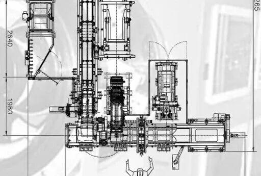
COMBI TBM drawing
COMBI TBM drawing

The COMBI integrates first-stage and second-stage building into one fully automatic system:

  • Cycle time: 35 seconds per tire; footprint: 11 m × 12 m
  • Max daily output: 2,000 green tires; only 1 operator.

COMBI serves PCR passenger and LT light truck tires, integrating first and second-stage building into a single fully automatic machine — no manual intervention, one complete green tire every 35 seconds. The customer retains traditional two-stage process design freedom while gaining full automation. About 80% of the design derives from proven INTEREUROPEAN production equipment; the remaining 20% is custom-developed for this system. Timing analysis and 3D motion simulation ensure no wasted motion.

The machine has 5 parallel workstations, each with cycle time ≤35 seconds, sustaining one green tire every 35 seconds.

Workflow

  1. Station 1 (First-stage REC drum): Carcass components (inner liner, 1st ply, 2nd ply) are actively guided, cut to length, and applied to the REC drum. Inner liner uses adjustable-angle ultrasonic skew cut to avoid air entrapment. Multi-disc rollers exhaust air; side press wheels secure edges. Robot loads bead at cycle start for bead setting and turn-up. Second ply can be applied before or after turn-up for maximum design flexibility.
  2. Sidewall application station: Two independent ultrasonic knives apply and cut sidewalls on-drum (7/8 cut) with high splice precision; adjustable skew angles make near-invisible splices. Multi-disc rollers stitch; support idlers hold sidewall edges for uniform splices. Independent active guiding for both sidewalls. This station also performs final carcass rolling and automatic carcass unloading.

A dedicated transfer mechanism moves the carcass from first-stage drum to second-stage shaping drum without manual handling. The shaping drum receives the carcass and pre-shapes; the transfer ring brings the belt-tread assembly from the belt drum for application. The shaping drum has mechanical bead locking for precise bead positioning.

Belt-tread assembly is built on the rotating turret’s two independent belt drums, same process as the Uni-Stage machine: magnetic bottom splicing, HD camera active guiding, length verification, immediate nylon cap ply winding with tension control, tread from roll with on-drum ultrasonic cutting, multi-disc pressure-adjustable stitching. Final shaping, dynamic rolling, and green tire unloading complete the cycle.

COMBI Technical Parameters

Parameter COMBI-1320 COMBI-1524
Bead diameter 13–20″ 15–24″
Max green tire diameter 800 mm 1000 mm
Max bead setting width 600 mm 700 mm
Belt drum diameter 750 mm 980 mm
Max sidewall width 240 mm 260 mm
Belt width 280 mm 350 mm
Tread width 350 mm 450 mm
Cycle time per tire 35 s 40 s
Max daily output* ~2000 tires/day ~1500 tires/day
Operators 1 per machine 1 per machine
Footprint (2-ply) 11×12 m 12×13 m

3. Traditional First-Stage and Second-Stage TBMs

First-Stage TBM

Fully automatic first-stage building machine for PCR/LT tires. Active guiding, automatic cutting and application; finger-up + bladder turn-up; touchscreen monitoring with recipe management and fault diagnosis. Cycle time as low as 45 seconds. Operator performs visual inspection, removes built carcass at each cycle, and loads new beads. Customizable: 1/2 ply, steel/fiber chafer, sidewall from roll or cassette, gum strip pre-assembly.

Parameter Value
Bead diameter 13–17″ (opt. 15–20″)
Drum width 250–550 mm (opt. 250–600 mm)
Inner liner width 720 mm (opt. 800 mm)
Carcass ply width 720 mm (opt. 900 mm)
Max sidewall width 240 mm (opt. 300 mm)
Cycle time ~45 s
Operators 1
Footprint (2-ply) 5.78×9.69 m

Second-Stage TBM

Fully automatic second-stage building machine. Active guiding, automatic cutting; rotating turret with double belt drums for optimized tact; bead-lock shaping drum; tread from roll with ultrasonic cutting; optional nylon cap winder; touchscreen with recipe and diagnostics. Cycle time as low as 45 seconds. Transfer ring removes green tire.

Parameter Value
Bead diameter 13–17″ (opt. 15–20″)
Shaping drum type Bead-lock type
Max green tire width 780 mm (opt. 800 mm)
Belt width 250 mm (opt. 300 mm)
Belt cutting angle 18–30°
Tread width 300 mm (opt. 350 mm)
Belt drum diameter range 450–720 mm
Cycle time ~45 s
Operators 1
Footprint 7.40×10.27 m

4. Fully Automatic Bead Apexing Lines

Bead apexing line robot loading
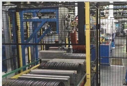

Bead apexing line overview

Available in PCR/LT version (13–22 inches) and TBR truck/bus version (17.5–24.5 inches). The new-generation fully automatic bead apexing line is based on multi-plant production experience. Key upgrades over previous semi-automatic models:

  • Recipe-driven automatic size changeover
  • Brushless motors with encoders (replacing photoelectric positioning)
  • Highly synchronized stable splicing system
  • 80 mm pin-barrel extruder for higher output on large beads
  • Constant-speed extruder for stable apex cross-section
  • Large-capacity tension accumulator
  • Adjustable splice presser fingers for uniform splices
  • Allen-Bradley PLC with remote diagnostics and MES integration
  • On-line apex height and splice quality visual inspection with statistical processing
  • Closed-loop chiller temperature control
  • Optional KUKA robot for automatic bead loading/unloading and isolator ring insertion

PCR/LT version: cycle time ≤10 seconds per bead (~6 beads/minute), 1 operator per shift. TBR version: 90+90 mm dual cold-feed extruder, air cooling, 20 seconds per bead, footprint 25 m × 9.5 m.

5. Bias Cutter & Splicer Lines
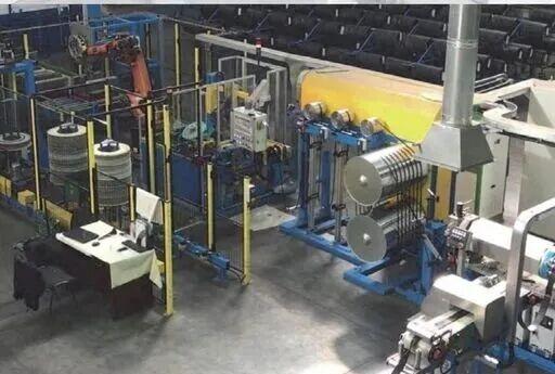
Bias cutter line
Bias cutter line

Fully automatic bias cutting and splicing line for steel and textile cord fabric. Cutting angle 40–90°; supports lap splicing and butt splicing. Includes unwind, accumulator, electronic centering, adjustable-angle knife, conveyor, and butt-splicing mechanism. Optional splice visual inspection, slitting, and rewind. Accuracy: splice tolerance ±0.5 mm; laser and CCD on-line monitoring. Output: variable-angle version up to 15 splices/minute; fixed 90° version up to 20 splices/minute.

6. Slitter Lines
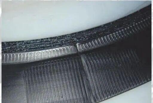
Slitter line layout
Slitter line layout

Slits wide rubber sheets into narrow strips for cap ply gum strip application:

  • Max raw width: 1000 mm; finished strip width: 20–300 mm
  • Line speed: 0–30 m/min; multi-disc knife slitting; BST active edge guiding
  • Width tolerance ±1 mm; max rewind roll diameter 600 mm
  • Allen-Bradley PLC, FESTO pneumatics; footprint 6.65×2.03 m

7. Uni-Stage Air Spring Production Line
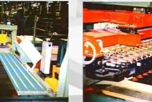
Air spring fatigue testing machine

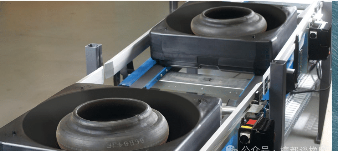
Complete automated equipment for truck and bus air suspension springs: Uni-Stage air spring building machine, first-stage and second-stage air spring building machines, pressing machines, leak testers, dual-station curing presses, crimping presses, fatigue testing machines, bead winding lines, bias cutters, inner liner calendering/extrusion lines.

The Uni-Stage air spring building machine produces a complete green air spring every 20 seconds, max daily output 3,600 pieces; supports convoluted and cylindrical air springs. Factory host-system integration and remote diagnostics; double-slide unwinds for non-stop roll changes; 3 operators, estimated 30-minute size changeover.

8. Equipment Upgrade, Retrofit, and Custom Services

Uni-Stage TBM general assembly drawing

0

Uni-Stage TBM general assembly drawing

1

Uni-Stage TBM general assembly drawing

2. INTEREUROPEAN also supplies upgrade and retrofit packages for existing second-stage building machines, plus custom engineering services.

 

Four SSBR Grades in High-Performance Tire Tread Compounds: A Comparative Study

This study compares four solution styrene-butadiene rubber (SSBR) grades (SOL5251H, SOL5360H, SOL5271H, SOL6440H from Kumho Petrochemical) in high-dispersible silica-filled tread compounds, evaluating processing, cure, mechanical properties, wet grip, rolling resistance, and wear.

Keywords: SSBR; solution SBR; high-performance tire; tread compound; wet grip; rolling resistance; silica; Payne effect

Introduction

Modern high-performance tires are judged on three core metrics: wet grip, rolling resistance, and wear. Each wet grip grade improvement shortens braking distance by 3–5 m; each rolling resistance grade improvement saves ~17 L gasoline per tire per 50,000 km (~68 L per vehicle). BR has low hysteresis and good wear but poor wet grip; NR has high strength but inadequate wet grip. SSBR offers controllable microstructure — styrene and vinyl content can be tuned independently. Higher vinyl content raises Tg for better wet grip without the heat buildup caused by high styrene. Narrow molecular weight distribution means fewer low-molecular-weight chains and lower hysteresis, making SSBR the preferred matrix for high-performance treads.

Experimental

Materials

Material Grade Supplier
SSBR (dual-end modified, non-oil-extended) SOL5251H Kumho Petrochem
SSBR (dual-end modified, non-oil-extended) SOL5360H Kumho Petrochem
SSBR (dual-end modified, non-oil-extended) SOL5271H Kumho Petrochem
SSBR (single-end modified, 37.5 phr treated distillate aromatic extract oil) SOL6440H Kumho Petrochem
High-dispersion silica HD165MP Fujian Zhengsheng

Formulation (phr): SSBR 100; silica 80; silane coupling agent 12.8; naphthenic oil 37.5; activator 5; antioxidant 3; sulfur 1.5; accelerator 4.

Mixing: Two-stage. First stage: 90 rpm, 60°C cooling, dump at 150°C. Second stage: 40 rpm, add sulfur + accelerator, dump ≤105°C. Cure: 161°C, 20 min (2 mm sheets / DIN abrasion), 30 min (mechanical specimens).

Results and Discussion

Raw Polymer Properties

Property 5251H 5360H 5271H 6440H
Styrene content 0.210 0.285 0.210 0.355
Vinyl (1,2-butadiene) content 0.43 0.41 0.50 0.26
Tg (°C) -30 -21 -24 -26
Mw (×10⁴) 47.9 43.8 45.3 110.9
PDI (Mw/Mn) 1.54 1.41 1.35 2.29

5360H has elevated styrene (higher Tg). 5271H keeps styrene at 5251H level but greatly increases vinyl. 6440H has the highest styrene and lowest vinyl, with very high Mw (1.1 million) and broader PDI — high green strength but harder processing. 5251H/5360H/5271H have narrow PDI, favoring low hysteresis.

Cure Characteristics

Property 5251H 5360H 5271H 6440H
Mooney ML(1+4)@100°C 73 73 76 88
Scorch t5 @127°C (min) 26.6 21.1 23.1 18.6
Fmax-FL (dN·m) 13.2 13.2 13.4 14.6

6440H has the highest Mooney viscosity (from massive molecular chain entanglement), shortest scorch time (narrower processing window), and highest crosslink density.

Physical Mechanical Properties

Property 5251H 5360H 5271H 6440H
Shore A hardness 59 59 58 62
M300% (MPa) 15.0 16.9 16.6 14.5
Tensile strength (MPa) 19.2 18.9 18.1 23.2
Elongation at break (%) 357 327 313 429
Tear strength (kN/m) 33 30 29 43
Rebound (%) 39 26 30 25
DIN abrasion index (higher=better) 149 125 139 141

6440H has the highest hardness, tensile, and tear strength due to ultra-high molecular weight. Compared to 5251H, 5360H and 5271H show higher M300 but lower rebound and wear — chain stiffness increases. 6440H’s single-end modification gives weaker filler-rubber interaction (lower M300 than 5271H) but its massive Mw delivers the best strength.

Dynamic Mechanical Properties

Property 5251H 5360H 5271H 6440H
Cured Tg (°C) -17 -9 -12 -12
tanδ @ 0°C (wet grip index) 0.555 0.902 0.755 0.722
tanδ @ 60°C (RR index) 0.088 0.093 0.091 0.101
Compression heat buildup (°C) 20.1 18.3 19.0 21.5
ΔG’ Payne effect (kPa) 557 535 440 1152

Wet grip ranking: 5360H > 5271H > 6440H > 5251H. Styrene content contributes more to 0°C tanδ than vinyl at similar Tg.

Rolling resistance: 5251H is best (lowest 60°C tanδ). Both higher styrene and higher vinyl slightly increase 60°C tanδ. Despite same raw Tg, 6440H has significantly higher RR than 5271H due to its strong filler network (Payne effect ΔG’ = 1152 kPa, more than double the others).

Conclusions

  1. SSBR5251H: Lowest Mooney, best processability; highest rebound and DIN wear; lowest rolling resistance; lowest Tg means weaker wet grip. Best for low-RR-oriented tread compounds.
  2. SSBR5360H: High styrene; processability similar to 5251H; higher M300, slightly lower wear; dramatically higher 0°C tanδ (best wet grip), with only modest RR penalty. Best for high-wet-grip treads.
  3. SSBR5271H: High-vinyl dual-end modified; higher M300, slightly lower wear; combines good wet grip with low rolling resistance — the balanced all-rounder.
  4. SSBR6440H: Ultra-high molecular weight, highest Mooney, shortest scorch, narrowest processing window; best tensile and tear strength, decent wear; same raw Tg as 5271H but strong Payne effect (poor silica dispersion) means higher RR and heat buildup.


Technologies to Reduce Tire Rolling Resistance

Reducing tire rolling resistance is one of the most effective ways to cut fuel costs and CO₂ emissions. This article explains how rolling resistance arises and the key technologies used to control it.

Keywords: tire rolling resistance; fuel-efficient tire; viscoelasticity; tan delta; silica; tire label; green tire

1. Introduction

Tires are the only component in contact with the road surface. Over the past decade, global vehicle parc has grown about 30%, driven by emerging markets in Asia. Rolling resistance accounts for 7–10% of fuel consumption in urban driving. A 30% reduction in rolling resistance translates to roughly 3% better fuel efficiency. Life-cycle analysis shows that 90% of a tire’s CO₂ emissions come from the use phase — fuel burned to overcome rolling resistance.

Driving Condition Tire Contribution to Fuel Use
Constant-speed cruising 20–25%
Cycle test 10–20%
Real urban driving 7–10%

2. Tire Labeling Regulations

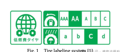
Tire labels inform consumers of performance levels and drive manufacturers to develop fuel-efficient tires. Japan introduced voluntary labeling for summer passenger tires in 2010. Tires rated A or above for rolling resistance and D or above for wet grip are classified as “fuel-efficient tires.”

Figure 1

3. Rolling Resistance: How It Arises

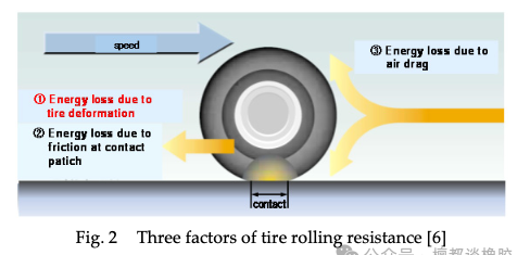
Rolling resistance comes from three sources:

  1. Energy loss from tire deformation — accounts for over 90% of total rolling resistance.
  2. Friction loss at the contact patch.
  3. Air drag.

As the tire rolls, the contact patch is flattened from its circular shape. The rubber undergoes large, repeated deformation, dissipating energy as heat. This repeated flexing heats the tire and consumes vehicle kinetic energy — the primary mechanism of rolling resistance.

Figure 2

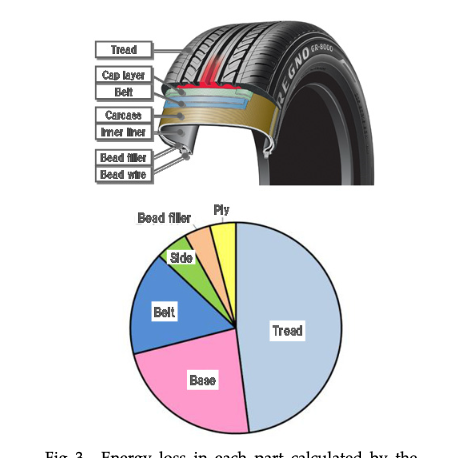
About half the tire’s weight is polymer, a quarter is filler, and the remaining quarter is rubber chemicals, reinforcement fibers, and steel cords. The tread contributes the most to rolling resistance because of its high rubber content. However, reducing tread energy loss tends to worsen grip — the core trade-off tire engineers must optimize.

Figure 3

The tan δ Connection

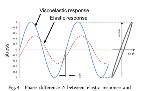
Rubber energy loss is measured by a viscoelastic analyzer using tan δ (the tangent of the phase angle δ between stress and strain). The hysteresis loop represents energy dissipated as heat. Tread compound design relies on a “property map”:

  • 30–50°C tan δ up → better dry grip
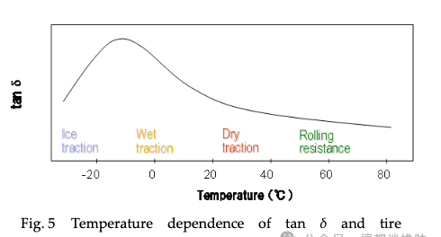
  • 0–10°C tan δ up → better wet grip
  • ~60°C tan δ down → lower rolling resistance

Figure 4

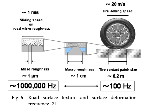
Critical insight: wet-road friction involves deformation frequencies of ~1,000,000 Hz (microscopic road roughness at 1µm scale), while rolling resistance operates at ~100 Hz (tire rotation). By the time-temperature superposition principle, high frequency = low temperature, and low frequency = high temperature. Therefore: wet grip is governed by low-temperature tan δ, while rolling resistance is governed by high-temperature tan δ — making it possible to optimize both independently.

Figure 5

4. Two Approaches to Reduce Rolling Resistance

Approach 1: Structural Design

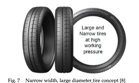
Increase tire diameter and inflation pressure to suppress deformation overall. A larger circular footprint reduces rubber flexing at the contact patch; narrower section width reduces rubber volume and energy loss. The trade-off: smaller contact patch reduces handling stability, requiring compound compensation. Large-diameter narrow tires require co-development with vehicle OEMs.

Figure 6

Approach 2: Compound Formulation

The core challenge is improving filler dispersion in the rubber matrix. Nanoscale FEM shows that under 15% macroscopic strain, filler agglomerations create local strain concentrations above 200% — a 10x amplification that causes enormous energy loss. Good dispersion eliminates these hotspots.

Figure 7

The mainstream solution is chain-end functionalized polymers: functional groups introduced at polymer chain ends interact strongly with filler surfaces (silica), suppressing agglomeration and improving dispersion. Electron tomography directly visualizes the dispersion quality. Japan’s NEDO project on “ultra-low-fuel-consumption tire 3D nanoscale rubber” uses simulation-based structural design to balance rolling resistance with wear and grip.

5. Conclusion

As vehicle parc grows in emerging markets, reducing tire rolling resistance will only become more important. Beyond tires, reducing friction in other vehicle components is a parallel R&D direction. Cross-disciplinary engineering collaboration is essential to lower overall vehicle friction, cut fuel costs, and reduce CO₂ emissions.